Introduction to Rotary Encoders
A rotary encoder is an electro-mechanical device that converts the angular position or motion of a shaft or axle to analog or digital output signals. Rotary encoders are widely used in various applications, such as industrial controls, robotics, automotive systems, and computer peripherals, to measure rotation, position, speed, and direction.
There are two main types of rotary encoders:
-
Absolute Encoders: These encoders provide a unique output code for each distinct angular position of the shaft. They maintain their position information even when power is removed, making them suitable for applications that require precise positioning and tracking.
-
Incremental Encoders: These encoders generate a series of pulses as the shaft rotates, allowing the system to determine the relative position, speed, and direction of rotation. They do not provide absolute position information and require a reference point to establish the initial position.
Advantages of Rotary Encoders
Rotary encoders offer several advantages over other position sensing methods:
- High resolution and accuracy
- Robust and reliable operation in harsh environments
- Long lifespan and low maintenance requirements
- Versatile output options (analog, digital, or serial communication)
- Easy integration with microcontrollers and digital systems
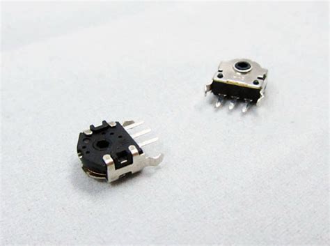
Mouse Rotary Encoder
A mouse rotary encoder is a type of incremental encoder commonly found in computer mice and other pointing devices. It is used to track the rotation of the scroll wheel, allowing users to navigate through documents, web pages, or other content quickly.
Components of a Mouse Rotary Encoder
A typical mouse rotary encoder consists of the following components:
-
Encoder Wheel: A disk with a series of evenly spaced slots or perforations around its circumference. The wheel is attached to the scroll wheel shaft and rotates with it.
-
Light Emitter: An LED or infrared light source that emits a beam of light towards the encoder wheel.
-
Light Detector: A phototransistor or photodiode that detects the light passing through the slots in the encoder wheel.
-
Quadrature Outputs: Two output channels (A and B) that generate quadrature signals as the encoder wheel rotates. These signals are used to determine the direction and speed of rotation.
Working Principle
The working principle of a mouse rotary encoder is based on the optical detection of the encoder wheel’s rotation. As the user turns the scroll wheel, the encoder wheel rotates, causing the slots to alternately block and allow the light from the emitter to reach the detector.
The light detector generates electrical pulses corresponding to the pattern of light and dark periods. These pulses are then processed by the microcontroller to determine the rotation direction and speed.
The quadrature outputs (A and B) are arranged so that they are 90 degrees out of phase with each other. By comparing the relative timing and sequence of the pulses on these channels, the microcontroller can determine the direction of rotation.
| Channel A | Channel B | Direction |
|---|---|---|
| Rising | Low | Clockwise |
| Falling | High | Clockwise |
| Low | Rising | Counterclockwise |
| High | Falling | Counterclockwise |
The speed of rotation is determined by counting the number of pulses within a given time interval. A higher pulse count indicates faster rotation, while a lower count represents slower rotation.

Connecting a Mouse Rotary Encoder to an Arduino
To interface a mouse rotary encoder with an Arduino, you’ll need to connect the encoder’s quadrature outputs to the Arduino’s digital input pins and use interrupts to detect the pulses.
Hardware Connection
-
Identify the pins on your mouse rotary encoder. Typically, there will be three pins: Ground (GND), Channel A, and Channel B.
-
Connect the GND pin to one of the Arduino’s GND pins.
-
Connect Channel A to a digital input pin on the Arduino, such as pin 2.
-
Connect Channel B to another digital input pin on the Arduino, such as pin 3.
-
If your encoder has a built-in pull-up resistor, you can leave the pins floating. Otherwise, connect a 10kΩ pull-up resistor between each channel and the Arduino’s 5V pin.
| Encoder Pin | Arduino Pin |
|---|---|
| GND | GND |
| Channel A | Digital Pin 2 |
| Channel B | Digital Pin 3 |
Software Implementation
To read the rotary encoder’s output and determine the rotation direction and speed, you’ll need to write a sketch for your Arduino. Here’s a basic example:
#define ENCODER_A 2
#define ENCODER_B 3

volatile int encoderCount = 0;

void setup() {
  pinMode(ENCODER_A, INPUT_PULLUP);
  pinMode(ENCODER_B, INPUT_PULLUP);
  attachInterrupt(digitalPinToInterrupt(ENCODER_A), handleEncoderInterrupt, CHANGE);
  Serial.begin(9600);
}

void loop() {
  Serial.println(encoderCount);
  delay(100);
}

void handleEncoderInterrupt() {
  if (digitalRead(ENCODER_A) == digitalRead(ENCODER_B)) {
    encoderCount++;
  } else {
    encoderCount--;
  }
}
In this example:
-
We define the pin numbers for the encoder’s Channel A and Channel B.
-
We create a volatile variable
encoderCountto store the current position of the encoder. -
In the
setup()function, we configure the encoder pins as inputs with pull-up resistors and attach an interrupt to Channel A. We also initialize the serial communication for debugging. -
In the
loop()function, we periodically print the current value ofencoderCountto the serial monitor. -
The
handleEncoderInterrupt()function is called whenever there is a change in the state of Channel A. It compares the states of Channel A and Channel B to determine the direction of rotation and increments or decrements theencoderCountaccordingly.
This basic implementation allows you to track the relative position of the encoder. You can further enhance the code to calculate the speed of rotation or implement additional features based on your specific application requirements.

Applications of Mouse Rotary Encoders
Mouse rotary encoders find applications in various fields, including:
-
Computer Peripherals: Used in computer mice, trackballs, and other pointing devices to enable scrolling and navigation control.
-
Audio and Video Equipment: Found in volume knobs, jog wheels, and other controls on audio mixers, video editing consoles, and DJ equipment.
-
Industrial Controls: Used in rotary switches, dials, and selector knobs in industrial control panels and machinery.
-
Automotive Systems: Employed in infotainment systems, climate controls, and other rotary input devices in vehicles.
-
Robotics and Automation: Used for position feedback and motion control in robotic arms, gears, and other mechanical systems.

Frequently Asked Questions (FAQ)
-
Q: What is the difference between an absolute and incremental rotary encoder?
A: An absolute encoder provides a unique output code for each angular position, while an incremental encoder generates pulses that allow relative position tracking. -
Q: How does a mouse rotary encoder determine the direction of rotation?
A: By comparing the relative timing and sequence of pulses on the quadrature output channels (A and B), the microcontroller can determine the direction of rotation. -
Q: Can I use a mouse rotary encoder with other microcontrollers besides Arduino?
A: Yes, you can interface a mouse rotary encoder with any microcontroller that has digital input capabilities and supports interrupts. -
Q: What is the typical resolution of a mouse rotary encoder?
A: The resolution of a mouse rotary encoder depends on the number of slots or perforations on the encoder wheel. Common resolutions range from 12 to 24 pulses per revolution. -
Q: How do I calculate the speed of rotation using a mouse rotary encoder?
A: To calculate the speed of rotation, you need to count the number of pulses within a fixed time interval. Dividing the pulse count by the time interval will give you the speed in pulses per second or revolutions per minute (RPM), depending on your encoder’s resolution.
Conclusion
Mouse rotary encoders are versatile and reliable devices for measuring rotation, position, and speed in various applications. By understanding their working principle and how to interface them with microcontrollers like Arduino, you can easily integrate rotary encoders into your projects and create interactive systems with precise rotary input capabilities.
When working with mouse rotary encoders, pay attention to the hardware connections, use appropriate pull-up resistors, and implement interrupt-based code for efficient and accurate rotation tracking. With the knowledge gained from this article, you can confidently incorporate mouse rotary encoders into your designs and unleash the potential of rotary input in your applications.
No responses yet