Introduction to MOSFET Relays
A MOSFET (metal-oxide-semiconductor field-effect transistor) relay, also known as a solid state relay (SSR), is an electronic switching device that uses a small control signal to switch a larger load current or voltage. Unlike electromechanical relays which use moving mechanical contacts, MOSFET relays have no moving parts and rely on semiconductor technology to perform the switching function.
MOSFET relays offer several advantages over traditional electromechanical relays:
- Faster switching speeds
- Silent operation
- Longer operating life (no mechanical wear)
- Smaller size and weight
- Greater shock and vibration resistance
- Compatible with microcontroller/logic level control signals
These benefits make MOSFET solid state relays an ideal choice for many applications requiring reliable high-speed switching of loads. Some common applications include:
- Industrial automation and process control
- Automotive and transportation systems
- Instrumentation and test equipment
- Medical devices
- Telecommunications infrastructure
- Renewable energy systems (solar inverters, wind turbines, etc.)
How MOSFET Relays Work
A MOSFET relay consists of an input control circuit, an opto-isolator, and one or more output MOSFET switches:
-
Input control circuit – Accepts a low-power DC control signal (3.3V to 24V) and drives an LED inside the opto-isolator when active. Usually includes protection against reverse polarity and over-voltage.
-
Opto-isolator – Provides galvanic isolation between the input control circuit and output switches. Contains an LED optically coupled to a photodetector. When the LED turns on, it activates the photodetector which then drives the MOSFET gates.
-
MOSFET output switches – Performs the actual power switching of the load. Can be designed for AC switching, DC switching, or both. MOSFETs have very low on-resistance (typically < 100 mΩ), enabling efficient switching of high load currents with minimal heat generation.
The basic switching operation is:
-
A DC voltage is applied to the input control pins, causing current to flow through the LED in the opto-isolator.
-
Light from the LED shines on the photodetector, causing it to conduct current. This current is used to charge the MOSFET gates.
-
Once the gate-source voltage exceeds the MOSFET threshold voltage, the MOSFETs turn on and conduct current through the load.
-
When the control input is removed, the photodetector stops conducting, allowing the MOSFET gates to discharge. The MOSFETs turn off and block current flow to the load.
The MOSFET output can be designed as normally-open (NO) or normally-closed (NC) switches. Multiple MOSFET switches can be integrated into a single package for switching multi-phase AC loads or for creating an AC/DC hybrid relay.
Galvanic Isolation
One of the key features of MOSFET relays is galvanic isolation between the input control and output load circuits. The opto-isolator provides a physical barrier that electrically separates the two sides, allowing them to be at very different voltage potentials.
Galvanic isolation provides several important benefits:
- Protects the control circuitry from high voltages and transients on the load side
- Prevents ground loops between the control and load circuits
- Allows the control and load to be referenced to different ground potentials
- Enables control of high-side switches in bridge configurations
MOSFET relays are available with various isolation voltage ratings, typically ranging from 1 kV to 5 kV. The specific rating needed depends on the application requirements and regulatory standards that must be met. Higher isolation voltages provide greater safety margins but usually come with increased cost and size.

AC vs DC Switching
MOSFET relays can be designed for switching either AC or DC loads. The choice depends on the type of electrical power being used in the application.
AC Switching
AC MOSFET relays are used to switch alternating current loads, such as motors, heaters, lamps, and solenoids. They typically utilize two back-to-back (anti-series) MOSFET switches for each output pole, with the MOSFETs gated on during alternate half-cycles of the AC waveform. This allows current to flow through the load in both directions.
A zero-cross circuit is often included to synchronize the MOSFET gating with the zero-voltage points of the AC waveform. This minimizes inrush currents and EMI when switching reactive loads.
Key specs for AC MOSFET relays include:
– Load voltage rating (e.g. 120 VAC, 240 VAC)
– Load current rating
– Surge current capability
– dV/dt and dI/dt ratings
– Off-state leakage current
– Maximum operating frequency
DC Switching
DC MOSFET relays are used to switch DC loads in applications like battery charging, DC motor control, solar inverters, and telecommunications power supplies. They utilize a single MOSFET switch per output pole, with the switch gated on to allow current flow and off to block reverse current.
Key specs for DC MOSFET relays include:
– Voltage rating
– Current rating
– On-resistance
– Off-state leakage current
– Turn-on/turn-off time
– dV/dt rating
Some MOSFET relays are designed for both AC and DC switching in a single package. These hybrid relays provide flexibility for use in applications where both types of power may be encountered.
Comparing MOSFET Relays to Other Types
MOSFET relays offer distinct advantages over electromechanical relays (EMRs) and other solid state relays like triacs and SCRs. Here’s a comparison of the key characteristics:
| Parameter | MOSFET Relay | EMR | Triac/SCR |
|---|---|---|---|
| Switching Speed | Fast (<1ms) | Slow (>5ms) | Fast (<1ms) |
| Expected Lifetime | Long (>1B cycles) | Short (<1M cycles) | Long (>1B cycles) |
| Input Control Power | Low (µW to mW) | High (>100mW) | Low (µW to mW) |
| Isolation | High (>1kV) | Low (<1kV) | Varies |
| Leakage Current | Low (nA to µA) | None | Medium (mA) |
| Output Distortion | Low | None | High |
| Noise Generation | Low | Medium to High | Medium |
| Sensitivity to dV/dt | Low to Medium | None | High |
| Size | Small | Large | Small |
| Cost | Medium to High | Low | Low to Medium |
EMRs have been widely used for decades and offer low cost and simplicity. However, they are large, slow, and wear out quickly in cycling applications. EMRs also generate significant acoustic noise and switching transients.
Triacs and SCRs are commonly used for AC power control but have several drawbacks. They can only switch at the zero-cross points, create higher output distortion, and are very sensitive to dV/dt transients. Triacs and SCRs also have higher leakage current than MOSFETs.
MOSFET relays provide the best combination of switching performance, reliability, and noise immunity. They do have higher upfront cost than EMRs but this is often offset by their longer operating life in demanding applications.
Protection Features
MOSFET relays often integrate various protection features to enhance reliability and robustness in harsh environments. Some common protection features include:
-
Overcurrent protection – Limits the maximum load current to protect the MOSFETs and load from damage due to short circuits or overloads. Implemented using fuses, PTCs, or active current limiting circuits.
-
Overvoltage protection – Clamps transient voltage spikes to a safe level to protect the MOSFETs. Implemented using transient voltage suppressors (TVS) or metal oxide varistors (MOV).
-
Overtemperature protection – Shuts down the relay if the internal temperature exceeds a safe limit, preventing thermal damage to the MOSFETs. Implemented using an integrated Temperature Sensor and comparator.
-
Reverse polarity protection – Blocks current flow if the DC control input or load is connected with reverse polarity. Implemented using a series diode or active polarity detection circuit.
-
dV/dt immunity – Prevents false triggering of the output MOSFETs due to rapid voltage transients coupled through the relay’s parasitic capacitances. Implemented by limiting the MOSFET gate drive impedance and adding filtering.
The specific protection features needed depend on the application requirements and the expected operating environment. More robust protection generally comes with trade-offs in size, cost, and on-state performance.
Packaging Options
MOSFET relays are available in a variety of package styles to suit different application needs. Some common package types include:
-
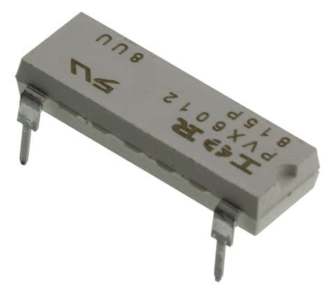
Through-hole DIP – Dual inline package with through-hole pins for PCB Mounting. Often used in low-power, low-cost applications.
-
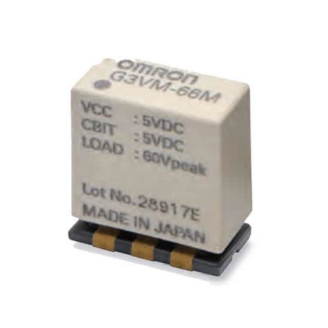
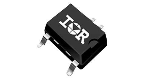
Surface-mount (SMT) – Smaller than through-hole and mounts directly to PCB pads. Enables higher power density and automated assembly.
-
Panel mount – Designed to be mounted to a panel or heatsink for applications requiring higher power dissipation. May have quick-connect terminals or wire leads.
-
Din rail mount – Allows snap-in mounting to standard 35mm DIN rails. Provides a convenient way to integrate multiple relays into industrial control panels.
-
Hazardous location – Designed with special sealing, insulation, and/or potting to prevent explosion hazards in flammable environments. Meets standards like UL1604 or ATEX.
-
High-voltage – Uses larger package with increased creepage/clearance distances to enable higher voltage isolation ratings.
When selecting a package, designers must consider the electrical specifications, thermal requirements, and mechanical constraints of the application. Trade-offs often need to be made between power density, ease of assembly, and cost.
Application Examples
Here are a few examples showcasing the use of MOSFET relays in real-world applications:
Industrial Automation
MOSFET relays are widely used in programmable logic controllers (PLCs), distributed control systems (DCS), and other industrial automation equipment. They provide a compact, reliable, and noise-immune way to interface low-voltage control signals to higher-power loads like motors, valves, and actuators.
For example, a 24V PLC output module may use MOSFET relays to switch 120/240 VAC pump motors based on the PLC’s control logic. The relays provide isolation between the PLC and motor circuits, and their fast switching enables precise control of the pumping process.
Automotive Battery Disconnect
In electric and hybrid vehicles, a high-voltage DC battery pack supplies energy to the traction motor inverter. For safety reasons, this battery must be physically disconnected from the rest of the vehicle when not in use or in the event of a crash.
A high-power DC MOSFET relay, rated for the full battery voltage and current, is commonly used as the main battery disconnect. The relay is controlled by the vehicle’s battery management system and provides a reliable means of isolating the battery with low conduction losses.
Solar Microinverters
Solar microinverters are small grid-tie inverters attached directly to individual PV modules. They convert the PV module’s DC output to grid-synchronized AC power, enabling more optimal energy harvesting and simpler installation compared to string inverters.
MOSFET relays are used in microinverters for several functions:
– Disconnecting the PV module and inverter from the grid for safety reasons
– Switching between different taps on the inverter’s transformer to optimize energy transfer
– Bypassing the microinverter during maintenance or in case of failure
The small size, high reliability, and arc-free switching of MOSFET relays make them ideal for meeting the demanding requirements of solar applications.
Frequently Asked Questions (FAQ)
1. What is the difference between a MOSFET relay and a conventional relay?
A MOSFET relay, also known as a solid state relay (SSR), uses semiconductor MOSFETs to perform the switching function, whereas a conventional electromechanical relay (EMR) uses moving mechanical contacts. MOSFET relays have no moving parts, making them faster, quieter, more shock resistant, and longer lasting compared to EMRs.
2. Can MOSFET relays switch both AC and DC loads?
Yes, MOSFET relays can be designed to switch either AC or DC loads, or both in the case of AC/DC hybrid relays. The specific design of the MOSFET output stage determines the relay’s load switching capability.
3. How much input control power do MOSFET relays require?
MOSFET relays require very little input control power, typically in the range of microwatts to milliwatts. This allows them to be easily driven by low-power microcontrollers, PLCs, or sensors. In contrast, EMRs require much higher control power, often exceeding 100 mW.
4. What is the isolation voltage rating of a MOSFET relay?
The isolation voltage rating specifies the maximum AC or DC voltage that can be applied between the relay’s input and output circuits without causing breakdown of the internal insulation. MOSFET relays are available with isolation ratings ranging from around 1 kV to over 5 kV, depending on the specific design and package.
5. How long do MOSFET relays last?
MOSFET relays have a very long operating life, typically exceeding 1 billion switching cycles. This is because they have no moving parts that can wear out or degrade over time. The actual lifetime in a given application depends on factors like the switched load current, ambient temperature, and switching frequency, but in general, MOSFET relays outlast EMRs by orders of magnitude.
Conclusion
MOSFET solid state relays offer numerous advantages over electromechanical relays and other SSR technologies. Their fast switching, silent operation, high reliability, and small size make them an ideal choice for applications demanding compact, robust, and efficient load switching.
As MOSFET technology continues to advance, we can expect to see even higher power density, integration, and performance from MOSFET relays in the future. This will enable new possibilities for smart, connected, and efficient control systems across a wide range of industries.
When selecting a MOSFET relay for a given application, designers must carefully consider the required electrical ratings, isolation level, protection features, and package type. By optimizing these parameters for the specific use case, designers can realize the full benefits of MOSFET relay technology in their end products.
No responses yet