Introduction to MCP41010 and Arduino
The MCP41010 is a digital potentiometer (digipot) that allows you to control resistance values using a microcontroller like an Arduino. This versatile component finds applications in various projects where variable resistance is required, such as audio volume control, LED brightness adjustment, or sensor calibration. In this article, we will explore how to interface the MCP41010 with an Arduino and demonstrate its functionality through practical examples.
What is a Digital Potentiometer?
A digital potentiometer, or digipot, is an electronic component that mimics the behavior of a traditional mechanical potentiometer. However, instead of manually adjusting the resistance by turning a knob, a digipot allows you to control the resistance value digitally using a microcontroller. The MCP41010 is a popular choice among hobbyists and engineers due to its ease of use and precise control.
Key Features of the MCP41010
The MCP41010 offers several notable features that make it an attractive choice for Arduino projects:
- 10 kΩ potentiometer with 256 taps (8-bit resolution)
- Single-channel design
- SPI interface for easy communication with microcontrollers
- Dual power supply operation (2.7V to 5.5V)
- Low power consumption
- Small form factor (8-pin DIP or SOIC package)
Interfacing MCP41010 with Arduino
To get started with the MCP41010 and Arduino, you’ll need the following components:
- Arduino board (e.g., Arduino Uno)
- MCP41010 digital potentiometer
- Breadboard
- Jumper wires
- USB cable for programming the Arduino
Wiring Connection
The MCP41010 communicates with the Arduino using the SPI (Serial Peripheral Interface) protocol. Here’s how you can connect the MCP41010 to your Arduino:
| MCP41010 Pin | Arduino Pin |
|---|---|
| CS | D10 |
| SDI | D11 |
| CLK | D13 |
| VCC | 5V |
| GND | GND |
Follow these steps to wire up the components:
- Place the MCP41010 on the breadboard.
- Connect the CS pin of the MCP41010 to digital pin 10 on the Arduino.
- Connect the SDI pin of the MCP41010 to digital pin 11 on the Arduino (MOSI).
- Connect the CLK pin of the MCP41010 to digital pin 13 on the Arduino (SCK).
- Connect the VCC pin of the MCP41010 to the 5V pin on the Arduino.
- Connect the GND pin of the MCP41010 to the GND pin on the Arduino.
Arduino Library Installation
To simplify the programming process, we will use the SPI.h library, which is already included in the Arduino IDE. No additional library installation is required.

Programming the MCP41010 with Arduino
Now that the hardware is set up, let’s dive into the programming aspect. We’ll start with a basic example that demonstrates how to control the resistance value of the MCP41010 using Arduino.
Example 1: Controlling Resistance Value
In this example, we will set the resistance value of the MCP41010 to a specific value and read the wiper voltage using an analog input pin on the Arduino.
#include <SPI.h>

const int csPin = 10; // Chip Select pin

void setup() {
  pinMode(csPin, OUTPUT);
  SPI.begin();
}

void setResistance(int value) {
  digitalWrite(csPin, LOW);
  SPI.transfer(B00010001); // Command byte: write data
  SPI.transfer(value);
  digitalWrite(csPin, HIGH);
}

void loop() {
  int value = 128; // Set resistance value (0-255)
  setResistance(value);

  int wiperVoltage = analogRead(A0);
  float voltage = wiperVoltage * (5.0 / 1023.0);

  Serial.print("Resistance value: ");
  Serial.print(value);
  Serial.print(", Wiper voltage: ");
  Serial.print(voltage);
  Serial.println(" V");

  delay(1000);
}
In this code:
1. We include the SPI.h library and define the Chip Select pin (csPin) as digital pin 10.
2. In the setup() function, we set the csPin as an output and initialize the SPI communication using SPI.begin().
3. We define a setResistance() function that takes the resistance value (0-255) as a parameter. It sends the command byte and the value to the MCP41010 via SPI.
4. In the loop() function, we set the resistance value to 128 (half of the maximum value) using the setResistance() function.
5. We read the wiper voltage using analogRead() on analog pin A0 and convert it to volts.
6. Finally, we print the resistance value and wiper voltage to the Serial Monitor.
Upload this code to your Arduino, open the Serial Monitor, and observe the output. You should see the resistance value and corresponding wiper voltage printed every second.
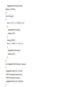
Example 2: Fading an LED
Let’s explore another example where we use the MCP41010 to control the brightness of an LED.
#include <SPI.h>

const int csPin = 10; // Chip Select pin
const int ledPin = 9; // LED pin

void setup() {
  pinMode(csPin, OUTPUT);
  pinMode(ledPin, OUTPUT);
  SPI.begin();
}

void setResistance(int value) {
  digitalWrite(csPin, LOW);
  SPI.transfer(B00010001); // Command byte: write data
  SPI.transfer(value);
  digitalWrite(csPin, HIGH);
}

void loop() {
  for (int i = 0; i <= 255; i++) {
    setResistance(i);
    analogWrite(ledPin, i);
    delay(10);
  }

  for (int i = 255; i >= 0; i--) {
    setResistance(i);
    analogWrite(ledPin, i);
    delay(10);
  }
}
In this example:
1. We connect an LED to digital pin 9 (ledPin) through a current-limiting resistor.
2. The setup() and setResistance() functions remain the same as in the previous example.
3. In the loop() function, we use two for loops to gradually increase and decrease the resistance value of the MCP41010 from 0 to 255 and back to 0.
4. We also use analogWrite() to set the brightness of the LED corresponding to the resistance value.
5. The delay(10) statement introduces a small pause between each step to create a smooth fading effect.
Upload this code to your Arduino and observe the LED gradually fading in and out, controlled by the MCP41010.

Frequently Asked Questions (FAQ)
-
Q: Can I use multiple MCP41010 devices with a single Arduino?
A: Yes, you can use multiple MCP41010 devices with a single Arduino by connecting each device to a different Chip Select (CS) pin. Make sure to modify the code accordingly to control each device independently. -
Q: What is the maximum voltage that can be applied to the MCP41010?
A: The MCP41010 can operate with a supply voltage range of 2.7V to 5.5V. It is important not to exceed the maximum voltage rating to avoid damaging the device. -
Q: How can I control the MCP41010 with a higher resolution than 8 bits?
A: The MCP41010 has a fixed resolution of 8 bits, providing 256 taps. If you require higher resolution, you can consider using other digital potentiometers with more taps, such as the MCP41050 (10 bits) or MCP41100 (12 bits). -
Q: Can I use the MCP41010 for audio applications?
A: Yes, the MCP41010 can be used for audio applications, such as volume control or audio signal attenuation. However, keep in mind that the MCP41010 has a maximum resistance of 10 kΩ, which may not be suitable for all audio circuits. Consider the specific requirements of your application when selecting a digital potentiometer. -
Q: Are there any limitations or considerations when using the MCP41010?
A: While the MCP41010 is a versatile component, there are a few limitations to consider: - The maximum wiper current is limited to 1 mA, so it may not be suitable for high-current applications.
- The resistance tolerance is ±20%, which means the actual resistance value may vary from the nominal value.
- The MCP41010 has a finite number of write cycles (approximately 100,000), so it may not be suitable for applications that require frequent resistance changes over an extended period.

Conclusion
The MCP41010 digital potentiometer is a powerful component that allows you to control resistance values using an Arduino or other microcontrollers. By interfacing the MCP41010 with an Arduino using the SPI protocol, you can easily incorporate variable resistance into your projects, enabling a wide range of applications such as audio control, LED brightness adjustment, and sensor calibration.
In this article, we explored the basics of the MCP41010, its key features, and how to wire it up with an Arduino. We also provided two practical examples that demonstrated how to control the resistance value and fade an LED using the MCP41010.
Remember to consider the specific requirements of your project when using the MCP41010, such as the voltage range, wiper current, and resistance tolerance. With its ease of use and precise control, the MCP41010 is a valuable addition to any electronics enthusiast’s toolkit.
So go ahead and experiment with the MCP41010 in your own projects, and unleash the potential of digital potentiometers in your Arduino applications!
No responses yet