What is the MCP3008?
The MCP3008 is an 8-channel, 10-bit analog-to-digital converter manufactured by Microchip Technology. It is designed to provide a simple interface between analog sensors and digital microcontrollers. The MCP3008 uses the SPI (Serial Peripheral Interface) protocol for communication, making it compatible with a wide range of microcontrollers and single-board computers.
Key features of the MCP3008:
- 8 input channels for analog signals
- 10-bit resolution (1024 distinct values)
- SPI interface for easy communication with microcontrollers
- Low power consumption
- Single supply operation (2.7V to 5.5V)
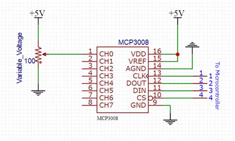
MCP3008 Pinout
To effectively use the MCP3008 ADC, it’s essential to understand its pinout and the function of each pin. The MCP3008 is available in a 16-pin DIP (Dual In-line Package) or a 16-pin SOIC (Small Outline Integrated Circuit) package. Here’s a detailed look at the MCP3008 pinout:
| Pin Number | Pin Name | Description |
|---|---|---|
| 1 | CH0 | Analog input channel 0 |
| 2 | CH1 | Analog input channel 1 |
| 3 | CH2 | Analog input channel 2 |
| 4 | CH3 | Analog input channel 3 |
| 5 | CH4 | Analog input channel 4 |
| 6 | CH5 | Analog input channel 5 |
| 7 | CH6 | Analog input channel 6 |
| 8 | CH7 | Analog input channel 7 |
| 9 | DGND | Digital ground |
| 10 | CS/SHDN | Chip select/Shutdown input |
| 11 | DIN | Data in (MOSI) |
| 12 | DOUT | Data out (MISO) |
| 13 | CLK | SPI clock input |
| 14 | AGND | Analog ground |
| 15 | VREF | Reference voltage input |
| 16 | VDD | Power supply (2.7V to 5.5V) |
Analog Input Channels (CH0-CH7)
The MCP3008 features 8 analog input channels, labeled CH0 through CH7. These pins are used to connect analog sensors or devices to the ADC. The analog voltage applied to these pins will be converted into a corresponding digital value by the MCP3008.
Digital and Analog Ground (DGND and AGND)
The MCP3008 has separate ground pins for digital and analog circuitry. DGND (pin 9) is the digital ground, while AGND (pin 14) is the analog ground. It’s important to connect these pins to the respective ground planes on your circuit board to ensure proper operation and minimize noise.
Chip Select/Shutdown (CS/SHDN)
The CS/SHDN pin (pin 10) serves two purposes:
-
Chip Select: When the CS/SHDN pin is pulled low, the MCP3008 is selected, and SPI communication can occur. When the pin is pulled high, the MCP3008 is deselected, and SPI communication is disabled.
-
Shutdown: If the CS/SHDN pin is pulled low for an extended period (>100 ms), the MCP3008 enters shutdown mode, reducing its power consumption to less than 5 μA. To exit shutdown mode, the CS/SHDN pin must be pulled high.
SPI Interface (DIN, DOUT, CLK)
The MCP3008 communicates with microcontrollers using the SPI protocol. The SPI interface consists of three pins:
-
DIN (pin 11): Data In, also known as MOSI (Master Out Slave In). This pin is used to send data from the microcontroller to the MCP3008.
-
DOUT (pin 12): Data Out, also known as MISO (Master In Slave Out). This pin is used to send data from the MCP3008 to the microcontroller.
-
CLK (pin 13): Clock input. This pin is used to synchronize the data transfer between the microcontroller and the MCP3008.
Reference Voltage (VREF)
The VREF pin (pin 15) is used to set the reference voltage for the analog-to-digital conversion. The voltage applied to this pin determines the maximum voltage that can be measured on the analog input channels. For example, if VREF is set to 5V, the analog input range will be 0V to 5V. If VREF is set to 3.3V, the analog input range will be 0V to 3.3V.
Power Supply (VDD)
The VDD pin (pin 16) is used to power the MCP3008. The ADC can operate on a supply voltage ranging from 2.7V to 5.5V. It’s important to ensure that the power supply is stable and free from noise to achieve accurate analog-to-digital conversions.
Interfacing the MCP3008 with a Microcontroller
To use the MCP3008 ADC with a microcontroller, you need to establish an SPI connection between the two devices. In this example, we’ll use an Arduino Uno to demonstrate the connection process.
Hardware Connection
- Connect the MCP3008 to the Arduino Uno as follows:
| MCP3008 Pin | Arduino Uno Pin |
|---|---|
| VDD | 5V |
| VREF | 5V |
| AGND | GND |
| CLK | SCK (pin 13) |
| DOUT | MISO (pin 12) |
| DIN | MOSI (pin 11) |
| CS/SHDN | SS (pin 10) |
| DGND | GND |
- Connect your analog sensors or devices to the appropriate analog input channels (CH0-CH7) on the MCP3008.
Software Configuration
To read analog values from the MCP3008 using an Arduino, you can use the built-in SPI library. Here’s a simple example sketch that demonstrates how to read a value from channel 0:
#include <SPI.h>

const int CS_PIN = 10;

void setup() {
  pinMode(CS_PIN, OUTPUT);
  digitalWrite(CS_PIN, HIGH);

  SPI.begin();
  Serial.begin(9600);
}

void loop() {
  digitalWrite(CS_PIN, LOW);
  SPI.transfer(0x01);
  int highByte = SPI.transfer(0x80);
  int lowByte = SPI.transfer(0x00);
  digitalWrite(CS_PIN, HIGH);

  int analogValue = ((highByte & 0x03) << 8) | lowByte;

  Serial.print("Analog value: ");
  Serial.println(analogValue);

  delay(1000);
}
In this example:
1. The CS_PIN is set to pin 10 on the Arduino Uno.
2. In the setup() function, the CS_PIN is set as an output and pulled high to deselect the MCP3008. The SPI and Serial communication are initialized.
3. In the loop() function, the following steps are performed:
– The MCP3008 is selected by pulling the CS_PIN low.
– The SPI.transfer() function is used to send the control byte and read the high and low bytes of the analog value from channel 0.
– The MCP3008 is deselected by pulling the CS_PIN high.
– The 10-bit analog value is reconstructed from the high and low bytes.
– The analog value is printed to the Serial Monitor.
– A delay of 1 second is added to control the reading rate.
By modifying the control byte, you can read analog values from different channels of the MCP3008.

Applications of the MCP3008 ADC
The MCP3008 ADC is versatile and can be used in a wide range of applications, including:
-
Sensor interfacing: The MCP3008 can be used to interface with various analog sensors, such as Temperature Sensors, light sensors, pressure sensors, and more. By converting the analog sensor readings to digital values, you can easily process and analyze the data using a microcontroller.
-
Analog signal monitoring: In industrial or scientific applications, the MCP3008 can be used to monitor analog signals from various sources, such as voltage levels, current levels, or other physical quantities. By periodically sampling the analog signals and converting them to digital values, you can track changes and trends in the monitored parameters.
-
Audio processing: The MCP3008 can be used in audio applications to digitize analog audio signals. By connecting a microphone or audio source to one of the analog input channels, you can sample the audio signal and process it using digital signal processing techniques.
-
Battery monitoring: The MCP3008 can be used to monitor battery voltage levels in battery-powered devices. By measuring the analog voltage of the battery and converting it to a digital value, you can estimate the remaining battery capacity and implement low-battery warnings or shutdown mechanisms.
-
Analog control systems: In control applications, the MCP3008 can be used to read analog inputs from sensors or potentiometers and use the digital values to control actuators, motors, or other devices. For example, you can use a potentiometer connected to the MCP3008 to control the speed of a DC motor or the brightness of an LED.
Tips for Using the MCP3008 ADC
To get the most out of your MCP3008 ADC and ensure accurate and reliable analog-to-digital conversions, consider the following tips:
-
Proper power supply: Ensure that the MCP3008 is powered with a stable and clean power supply within the specified voltage range (2.7V to 5.5V). Noisy or unstable power supplies can lead to inaccurate readings or even damage the ADC.
-
Grounding: Connect the digital and analog ground pins (DGND and AGND) to their respective ground planes on your circuit board. Proper grounding helps minimize noise and ensures accurate measurements.
-
Decoupling capacitors: Use decoupling capacitors close to the VDD and VREF pins to minimize power supply noise. A typical value for the decoupling capacitor is 0.1 μF.
-
Analog input range: Ensure that the analog input voltages applied to the MCP3008 channels are within the specified range (0V to VREF). Exceeding the maximum input voltage can damage the ADC.
-
Sampling rate: Choose an appropriate sampling rate based on the bandwidth of your analog signals. Oversampling can help improve the signal-to-noise ratio, but it also increases the processing overhead.
-
Analog signal conditioning: If your analog signals are noisy or have a high impedance, consider using analog signal conditioning techniques, such as amplification, filtering, or buffering, before connecting them to the MCP3008.
-
SPI communication: Ensure that your microcontroller’s SPI library is correctly configured and that the SPI clock speed is compatible with the MCP3008’s maximum clock frequency (1.35 MHz at 5V, 1.2 MHz at 2.7V).
-
Calibration: If high accuracy is required, consider calibrating your MCP3008 ADC using known reference voltages. This can help compensate for any offset or gain errors in the ADC’s measurements.
Frequently Asked Questions (FAQ)
-
What is the resolution of the MCP3008 ADC?
The MCP3008 ADC has a resolution of 10 bits, which means it can represent analog voltages with 1024 (2^10) distinct digital values. -
Can I use the MCP3008 with a 3.3V microcontroller?
Yes, the MCP3008 can operate with a power supply voltage ranging from 2.7V to 5.5V, making it compatible with both 3.3V and 5V microcontrollers. -
How do I select a specific channel to read from on the MCP3008?
To select a specific channel to read from, you need to send the appropriate control byte to the MCP3008 via SPI. The control byte consists of a start bit, single-ended/differential mode selection, channel selection bits, and don’t care bits. -
Can I use the MCP3008 for measuring negative voltages?
No, the MCP3008 is designed to measure positive voltages between 0V and VREF. If you need to measure negative voltages, you’ll need to use a different ADC or apply an offset to shift the negative voltages into the positive range. -
What is the maximum sampling rate of the MCP3008?
The maximum sampling rate of the MCP3008 depends on the SPI clock frequency and the microcontroller’s processing speed. With a 5V power supply, the maximum SPI clock frequency is 1.35 MHz, allowing for a theoretical maximum sampling rate of approximately 200 ksps (kilosamples per second). However, the actual sampling rate may be lower due to the microcontroller’s processing overhead and other factors.
Conclusion
The MCP3008 ADC is a powerful and versatile tool for interfacing analog sensors and devices with digital microcontrollers. By understanding the MCP3008 pinout, its functionality, and how to use it in your projects, you can unlock a wide range of applications and possibilities. Whether you’re working on sensor monitoring, audio processing, or analog control systems, the MCP3008 provides a simple and effective solution for analog-to-digital conversion.
Remember to follow best practices when using the MCP3008, such as ensuring proper power supply, grounding, and analog signal conditioning. With the right setup and configuration, the MCP3008 can provide accurate and reliable measurements, enabling you to build robust and efficient analog-to-digital systems.
So go ahead and experiment with the MCP3008 ADC in your projects, and unlock the potential of analog-to-digital conversion!
No responses yet