Introduction to Logic Gates and Truth Tables
Logic gates are the fundamental building blocks of digital electronics. They are used to perform logical operations on binary inputs (0s and 1s) and produce a single binary output. Truth tables are a way to represent the behavior of logic gates by showing all possible combinations of inputs and their corresponding outputs. In this comprehensive guide, we will explore the different types of logic gates, their truth tables, and their applications in digital circuits.
What are Logic Gates?
Logic gates are electronic circuits that perform logical operations on one or more binary inputs to produce a single binary output. They are the basic components of digital systems, such as computers, smartphones, and other electronic devices. Logic gates are implemented using transistors, which are semiconductor devices that can switch between two states: on (1) and off (0).
Why are Truth Tables Important?
Truth tables are essential for understanding the behavior of logic gates. They provide a visual representation of all possible combinations of inputs and their corresponding outputs. By analyzing truth tables, we can determine the logical function of a given gate and predict its output for any given set of inputs. Truth tables are also useful for designing and troubleshooting digital circuits.
Types of Logic Gates and Their Truth Tables
There are several types of logic gates, each with its own unique function and truth table. Let’s explore the most common logic gates and their truth tables.
AND Gate
The AND gate is a logic gate that performs the logical AND operation on two or more binary inputs. The output of an AND gate is 1 only if all its inputs are 1; otherwise, the output is 0.
AND Gate Truth Table
| Input A | Input B | Output |
|---|---|---|
| 0 | 0 | 0 |
| 0 | 1 | 0 |
| 1 | 0 | 0 |
| 1 | 1 | 1 |
OR Gate
The OR gate is a logic gate that performs the logical OR operation on two or more binary inputs. The output of an OR gate is 1 if at least one of its inputs is 1; otherwise, the output is 0.
OR Gate Truth Table
| Input A | Input B | Output |
|---|---|---|
| 0 | 0 | 0 |
| 0 | 1 | 1 |
| 1 | 0 | 1 |
| 1 | 1 | 1 |
NOT Gate (Inverter)
The NOT gate, also known as an inverter, is a logic gate that performs the logical NOT operation on a single binary input. The output of a NOT gate is the opposite of its input: if the input is 1, the output is 0, and vice versa.
NOT Gate Truth Table
| Input | Output |
|---|---|
| 0 | 1 |
| 1 | 0 |
NAND Gate
The NAND gate is a logic gate that performs the logical NAND (NOT-AND) operation on two or more binary inputs. The output of a NAND gate is 0 only if all its inputs are 1; otherwise, the output is 1.
NAND Gate Truth Table
| Input A | Input B | Output |
|---|---|---|
| 0 | 0 | 1 |
| 0 | 1 | 1 |
| 1 | 0 | 1 |
| 1 | 1 | 0 |
NOR Gate
The NOR gate is a logic gate that performs the logical NOR (NOT-OR) operation on two or more binary inputs. The output of a NOR gate is 1 only if all its inputs are 0; otherwise, the output is 0.
NOR Gate Truth Table
| Input A | Input B | Output |
|---|---|---|
| 0 | 0 | 1 |
| 0 | 1 | 0 |
| 1 | 0 | 0 |
| 1 | 1 | 0 |
XOR Gate (Exclusive OR)
The XOR gate, or Exclusive OR gate, is a logic gate that performs the logical XOR operation on two binary inputs. The output of an XOR gate is 1 only if exactly one of its inputs is 1; otherwise, the output is 0.
XOR Gate Truth Table
| Input A | Input B | Output |
|---|---|---|
| 0 | 0 | 0 |
| 0 | 1 | 1 |
| 1 | 0 | 1 |
| 1 | 1 | 0 |
XNOR Gate (Exclusive NOR)
The XNOR gate, or Exclusive NOR gate, is a logic gate that performs the logical XNOR operation on two binary inputs. The output of an XNOR gate is 1 if both inputs are the same (either both 0 or both 1); otherwise, the output is 0.
XNOR Gate Truth Table
| Input A | Input B | Output |
|---|---|---|
| 0 | 0 | 1 |
| 0 | 1 | 0 |
| 1 | 0 | 0 |
| 1 | 1 | 1 |

Combination of Logic Gates
Logic gates can be combined to create more complex digital circuits that perform specific functions. By understanding the truth tables of individual gates, we can analyze the behavior of these combinations and design circuits that meet our requirements.
Example: Half Adder
A half adder is a digital circuit that performs the addition of two single-bit binary numbers (A and B) and produces a sum (S) and a carry (C) output. It can be implemented using an XOR gate for the sum and an AND gate for the carry.
Half Adder Truth Table
| Input A | Input B | Sum (S) | Carry (C) |
|---|---|---|---|
| 0 | 0 | 0 | 0 |
| 0 | 1 | 1 | 0 |
| 1 | 0 | 1 | 0 |
| 1 | 1 | 0 | 1 |
Example: Full Adder
A full adder is a digital circuit that performs the addition of three single-bit binary numbers (A, B, and a carry-in, Cin) and produces a sum (S) and a carry-out (Cout). It can be implemented using two half adders and an OR gate.
Full Adder Truth Table
| Input A | Input B | Carry-in (Cin) | Sum (S) | Carry-out (Cout) |
|---|---|---|---|---|
| 0 | 0 | 0 | 0 | 0 |
| 0 | 0 | 1 | 1 | 0 |
| 0 | 1 | 0 | 1 | 0 |
| 0 | 1 | 1 | 0 | 1 |
| 1 | 0 | 0 | 1 | 0 |
| 1 | 0 | 1 | 0 | 1 |
| 1 | 1 | 0 | 0 | 1 |
| 1 | 1 | 1 | 1 | 1 |

Applications of Logic Gates and Truth Tables
Logic gates and truth tables have numerous applications in digital electronics and computer science. Some of these applications include:
-
Arithmetic Logic Units (ALUs): ALUs are the core components of processors that perform arithmetic and logical operations on binary data. They use a combination of logic gates to perform these operations based on the truth tables of the gates.
-
Digital Circuits: Logic gates are the building blocks of digital circuits. By combining different gates according to their truth tables, designers can create circuits that perform specific functions, such as multiplexers, demultiplexers, encoders, and decoders.
-
Boolean Algebra: Truth tables are closely related to Boolean algebra, which is a branch of mathematics that deals with the manipulation of logical expressions. Boolean algebra is used to simplify and optimize digital circuits by applying logical rules and theorems.
-
Computer Programming: Logic gates and truth tables are fundamental concepts in computer programming. Logical operators, such as AND (&&), OR (||), and NOT (!), are used in programming languages to make decisions and control the flow of programs based on the truth values of conditions.
-
Digital Communication: Logic gates and truth tables are used in digital communication systems to encode, transmit, and decode binary data. For example, error-correcting codes, such as Hamming codes, use the properties of XOR gates to detect and correct errors in transmitted data.

Frequently Asked Questions (FAQ)
- What is the difference between a logic gate and a truth table?
-
A logic gate is a physical electronic circuit that performs a logical operation on binary inputs, while a truth table is a visual representation of the behavior of a logic gate, showing all possible combinations of inputs and their corresponding outputs.
-
Can a logic gate have more than two inputs?
-
Yes, some logic gates, such as AND, OR, NAND, and NOR gates, can have multiple inputs. The number of inputs depends on the specific implementation of the gate.
-
What is the purpose of the NOT gate?
-
The NOT gate, also known as an inverter, is used to invert the state of a single binary input. It converts a 0 to a 1 and a 1 to a 0, which is useful for creating complementary signals and implementing logical negation in digital circuits.
-
How do I read a truth table?
-
To read a truth table, look at the input columns and find the row that corresponds to the specific combination of inputs you are interested in. The output column in that row will give you the corresponding output value for that combination of inputs.
-
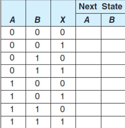
Can truth tables be used for circuits with sequential logic?
- Truth tables are primarily used for combinational logic circuits, where the output depends only on the current inputs. For sequential logic circuits, which have memory and whose output depends on both the current inputs and the previous state, other tools such as state transition tables and timing diagrams are used in addition to truth tables.
Conclusion
Logic gates and truth tables are essential concepts in digital electronics and computer science. They provide the foundation for understanding how binary data is processed and manipulated in digital systems. By mastering the different types of logic gates and their truth tables, you can design, analyze, and troubleshoot digital circuits effectively. Whether you are a student, a hobbyist, or a professional, a solid grasp of logic gates and truth tables will serve you well in the world of digital technology.
No responses yet