Key Features of the lm3915
The lm3915 offers several key features that make it a popular choice for various applications:
- Drives LEDs directly
- Bar or dot display mode externally selectable by user
- Expandable to displays of 100 steps
- Internal voltage reference from 1.2V to 12V
- Operates with single supply of less than 3V
- Inputs operate down to ground
- Output current programmable from 2 mA to 30 mA
- No multiplex switching or interaction between outputs
- Input withstands ±35V without damage or false outputs
- Outputs are current regulated, open collectors
- Directly drives TTL or CMOS
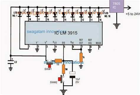
lm3915 Block Diagram
The block diagram above illustrates the internal architecture of the lm3915. The device consists of a precision voltage divider, a voltage reference, 10 comparators, and 10 output drivers.

Absolute Maximum Ratings
The following table lists the absolute maximum ratings for the lm3915:
| Parameter | Value | Unit |
|---|---|---|
| Power Supply Voltage | 25 | V |
| Input Signal Overvoltage | ±35 | V |
| Divider Voltage | −100 | mV |
| Reference Load Current | 10 | mA |
| Storage Temperature Range | −55 to 150 | °C |
Exceeding these ratings may cause permanent damage to the device. Exposure to absolute maximum conditions for extended periods may degrade device reliability.

Electrical Characteristics
The table below provides the electrical characteristics of the lm3915 under the recommended operating conditions:
| Parameter | Conditions | Min | Typ | Max | Unit |
|---|---|---|---|---|---|
| Input Signal Range | Pin 5 voltage | − | − | 0 to 12 | V |
| Divider Resistance | Pins 6 to 4 | − | 1 | − | kΩ |
| Divider Nonlinearity | − | − | 0.5 | 2 | % |
| Divider Input Current | Pin 5 input = 12V | − | 0.2 | 1 | µA |
| Output Voltage | ILED = 2 mA | − | 1.2 | 1.5 | V |
| Output Current | VLED = 2V | − | 7 | 10 | mA |
| LED Current Regulation | VLED = 2V to 17V | − | 0.2 | 1 | mA |
| Reference Voltage | − | 1.2 | 1.28 | 1.34 | V |
| Reference Adjust Range | Voltage at Pin 7 | 1.2 | − | 12 | V |
| Reference Adjust Input Current | Pin 7 input = 1.28V | − | 0.5 | 5 | µA |
| Supply Current | VCC = 5V, IL(ref) = 0 | − | 2.4 | 4 | mA |
These characteristics are specified for a temperature range of 0°C to 70°C, unless otherwise noted.

lm3915 Applications
The lm3915 finds use in a wide range of applications, including:
- Audio level meters
- Battery voltage monitors
- Temperature indicators
- Pressure gauges
- Light intensity meters
- Speedometers
- Tachometers
- Signal strength indicators
Its logarithmic response makes it particularly well-suited for audio applications, where the human ear perceives sound levels on a logarithmic scale.
Audio Level Meter Example
One common application of the lm3915 is in audio level meters. The circuit below shows a typical implementation:
In this circuit, the audio signal is AC-coupled to the input of the lm3915 through capacitor C1. Resistors R1 and R2 set the input sensitivity, while capacitor C2 provides filtering. The reference voltage is set by the voltage divider formed by resistors R3 and R4. Capacitor C3 bypasses the reference voltage for stability.
The LEDs are connected to the outputs of the lm3915, with current-limiting resistors R5 through R14. As the input signal level increases, more LEDs will illuminate, providing a visual indication of the audio level.
Cascading Multiple lm3915s
For applications requiring more than 10 LEDs, multiple lm3915s can be cascaded to expand the display range. The diagram below illustrates the connection of two lm3915s for a 20-LED display:
In this configuration, the first lm3915 drives LEDs 1 through 10, while the second lm3915 drives LEDs 11 through 20. The reference voltage of the second lm3915 is set by the REF OUT pin of the first lm3915. This ensures that the voltage thresholds for the two devices are properly aligned.
Additional lm3915s can be added in a similar manner to further expand the display range. Up to 10 devices can be cascaded for a total of 100 LEDs.
PCB Layout Considerations
When designing a PCB for the lm3915, several layout considerations should be taken into account:
- Bypass capacitors should be placed as close as possible to the VCC and GND pins of the lm3915.
- The reference voltage bypass capacitor should be located near the REF OUT and REF ADJ pins.
- Input signal traces should be kept as short as possible to minimize noise pickup.
- LED current-limiting resistors should be placed close to the lm3915 output pins.
- If using a dot mode display, the LED anodes should be connected directly to the lm3915 outputs. For bar mode displays, the LED cathodes should be connected to the outputs.
- Adequate copper pour should be used for power supply and ground planes to minimize voltage drops and improve heat dissipation.
By following these guidelines, you can ensure optimal performance and reliability of your lm3915-based designs.
Frequently Asked Questions (FAQ)
-
What is the difference between the lm3914 and lm3915?
The main difference between the lm3914 and lm3915 is their output response. The lm3914 provides a linear output, with each LED representing a fixed voltage increment. The lm3915, on the other hand, has a logarithmic output response, with each LED representing a 3 dB step in voltage. This makes the lm3915 more suitable for audio applications, where the human ear perceives sound levels logarithmically. -
Can the lm3915 be used with a negative supply voltage?
No, the lm3915 is designed for single-supply operation and requires a positive supply voltage. The minimum supply voltage is 3V, and the maximum is 25V. If a negative supply is required, a separate inverting circuit must be used to generate the negative voltage. -
How do I set the reference voltage for the lm3915?
The reference voltage for the lm3915 is set using the REF ADJ pin (pin 7). By connecting a potentiometer or a resistor divider between the REF OUT pin (pin 8) and ground, the reference voltage can be adjusted from 1.2V to 12V. The exact value of the reference voltage determines the voltage range of the display. -
What is the maximum number of LEDs that can be driven by a single lm3915?
A single lm3915 can drive up to 10 LEDs directly. However, by cascading multiple lm3915s, the display range can be expanded to 100 LEDs or more. Each additional lm3915 adds another 10 LEDs to the display. -
How do I select between bar mode and dot mode operation?
The display mode of the lm3915 is selected using the MODE pin (pin 9). When the MODE pin is connected to ground, the display operates in bar mode, where all LEDs up to the current input level are illuminated. When the MODE pin is connected to VCC, the display operates in dot mode, where only the LED corresponding to the current input level is illuminated.
Conclusion
The lm3915 is a versatile and easy-to-use integrated circuit for driving LED displays in a logarithmic manner. Its wide input voltage range, adjustable reference voltage, and cascadable architecture make it suitable for a variety of applications, from audio level meters to battery voltage monitors.
By understanding the features, specifications, and application circuits provided in the lm3915 Datasheet, designers can effectively incorporate this device into their projects. Proper PCB layout techniques and attention to the electrical characteristics will ensure optimal performance and reliability.
For more detailed information, please refer to the official lm3915 datasheet from the manufacturer.
No responses yet