Introduction to the LM3914
The LM3914 is a versatile and widely used integrated circuit (IC) that serves as a dot/bar display driver. It is designed to control and drive linear arrays of light-emitting diodes (LEDs) or vacuum fluorescent displays (VFDs) for various applications, such as audio level meters, battery charge indicators, and voltage monitors. This guide will provide a comprehensive overview of the LM3914, explaining how it works, its key features, and how to use it in your projects.
Key Features of the LM3914
The LM3914 offers several key features that make it an attractive choice for driving LED or VFD displays:
-
10-step linear display: The LM3914 can drive up to 10 LEDs or VFD segments in a linear fashion, providing a visual representation of an analog input signal.
-
Adjustable reference voltage: The IC allows you to set the reference voltage, which determines the input voltage range and the threshold for each LED or VFD segment.
-
Dot or bar mode: The LM3914 can be configured to operate in either dot mode (only one LED illuminated at a time) or bar mode (all LEDs up to the current level are illuminated).
-
Adjustable brightness: The LED or VFD brightness can be easily adjusted using an external resistor, allowing you to control the display intensity.
-
Cascadable: Multiple LM3914 ICs can be cascaded to create displays with more than 10 steps, enabling larger and more complex display configurations.

How the LM3914 Works
The LM3914 operates by comparing the input signal voltage to a series of 10 internal voltage dividers. Each voltage divider is connected to a comparator, which determines whether the input voltage is higher or lower than the reference voltage for that particular step. The comparator outputs are then used to drive the corresponding LED or VFD segment.
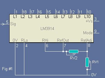
The input signal is applied to pin 5 (Signal Input) of the LM3914, while the reference voltage is set using an external resistor divider network connected to pin 6 (RHI) and pin 4 (RLO). The reference voltage determines the input voltage range and the threshold for each LED or VFD segment.
The LM3914 can be configured to operate in either dot mode or bar mode using pin 9 (Mode Select). In dot mode, only the LED or VFD segment corresponding to the current input voltage level is illuminated. In bar mode, all LEDs or VFD segments up to the current level are illuminated, creating a bar graph effect.
The brightness of the LEDs or VFD segments can be adjusted using an external resistor connected to pin 7 (Ref Out) and pin 8 (Ref Adj). This allows you to control the display intensity to suit your application’s requirements.

Typical Applications of the LM3914
The LM3914 finds use in a wide range of applications, including:
- Audio level meters
- Battery charge indicators
- Voltage monitors
- Temperature displays
- Pressure gauges
- Speed indicators
- Signal strength meters

Pinout and Pin Functions
The LM3914 is available in various package types, including DIP-18 and SOIC-18. The pinout and pin functions are as follows:
| Pin Number | Pin Name | Description |
|---|---|---|
| 1 | LED1 | LED/VFD segment 1 output |
| 2 | LED2 | LED/VFD segment 2 output |
| 3 | LED3 | LED/VFD segment 3 output |
| 4 | RLO | Low end of external resistor divider |
| 5 | Signal In | Analog input signal |
| 6 | RHI | High end of external resistor divider |
| 7 | Ref Out | Reference output for brightness adjustment |
| 8 | Ref Adj | Reference adjust for brightness control |
| 9 | Mode | Dot/Bar mode select (Dot: HIGH, Bar: LOW) |
| 10 | LED10 | LED/VFD segment 10 output |
| 11 | LED9 | LED/VFD segment 9 output |
| 12 | LED8 | LED/VFD segment 8 output |
| 13 | LED7 | LED/VFD segment 7 output |
| 14 | LED6 | LED/VFD segment 6 output |
| 15 | LED5 | LED/VFD segment 5 output |
| 16 | LED4 | LED/VFD segment 4 output |
| 17 | V+ | Positive supply voltage |
| 18 | GND | Ground |
Basic Circuit Configuration
To use the LM3914 in your project, you’ll need to set up a basic circuit that includes the following components:
- LM3914 IC
- LED or VFD display (up to 10 segments)
- External resistor divider for setting the reference voltage
- Brightness adjustment resistor
- Power supply (typically 3V to 25V)
Here’s a simple example circuit using the LM3914 to drive a 10-segment LED bar graph:
         +V
          |
         +-+
         | |
         | | R1
         | |
         +-+
          |
   +------+------+
   |     RHI     |
   |             |
   |   LM3914    |
   |             |
   |     RLO     |
   |             |
   |   Signal In |<--- Input Signal
   |             |
   |   Ref Out   |---+
   |             |   |
   |   Ref Adj   |   |
   |             |   |
   |     Mode    |   |
   |             |   |
   |    LED1     |---+--- LED1
   |     ...     |   |
   |    LED10    |---+--- LED10
   |             |
   |      V+     |------- +V
   |             |
   |     GND     |------- GND
   +------+------+
          |
          +--------- GND
In this example, R1 is the brightness adjustment resistor, and the input signal is connected to the “Signal In” pin. The reference voltage divider (RHI and RLO) is not shown for simplicity but should be included in your actual circuit.
Cascading Multiple LM3914 ICs
For applications requiring more than 10 LED or VFD segments, you can cascade multiple LM3914 ICs to create larger displays. To do this, connect the “RHI” pin of the second LM3914 to the “Ref Out” pin of the first LM3914, and so on for additional ICs. This allows the reference voltage to be shared among all the cascaded ICs, ensuring a consistent display.
Frequently Asked Questions (FAQ)
-
Q: Can I use the LM3914 with a microcontroller?
A: Yes, you can easily interface the LM3914 with a microcontroller by connecting the analog input signal to one of the microcontroller’s analog output pins (e.g., PWM or DAC). -
Q: How do I set the reference voltage for the LM3914?
A: The reference voltage is set using an external resistor divider connected to the “RHI” and “RLO” pins. The voltage at the “RHI” pin determines the upper limit of the input voltage range, while the voltage at the “RLO” pin determines the lower limit. -
Q: What is the maximum number of LEDs or VFD segments I can drive with the LM3914?
A: A single LM3914 can drive up to 10 LEDs or VFD segments. However, you can cascade multiple LM3914 ICs to create larger displays with more segments. -
Q: Can I use the LM3914 with a single power supply?
A: Yes, the LM3914 can operate with a single power supply ranging from 3V to 25V. Make sure to connect the “V+” pin to the positive supply voltage and the “GND” pin to ground. -
Q: How do I switch between dot mode and bar mode on the LM3914?
A: To switch between dot mode and bar mode, use the “Mode” pin. Connect the “Mode” pin to a high voltage (e.g., V+) for dot mode or to a low voltage (e.g., GND) for bar mode.
Conclusion
The LM3914 is a powerful and versatile IC that simplifies the process of driving linear LED or VFD displays. By understanding how the LM3914 works and how to configure it for your specific application, you can create visually appealing and informative displays for a wide range of projects. This guide has provided a comprehensive overview of the LM3914, including its key features, pinout, basic circuit configuration, and frequently asked questions. Armed with this knowledge, you can confidently incorporate the LM3914 into your next project and create stunning LED or VFD displays with ease.
No responses yet