Introduction to the LM386 Low Voltage Audio Power Amplifier
The LM386 is a popular low voltage audio power amplifier IC that is widely used in various audio applications. It is known for its ease of use, low cost, and decent audio quality. The LM386 can deliver up to 0.5W of output power into an 8Ω load, making it suitable for small-scale audio projects such as portable speakers, intercoms, and guitar amplifiers.
Key Features of the LM386
- Low supply voltage range: 4V to 12V
- Low quiescent current drain: 4mA
- Voltage gains from 20 to 200
- 8-pin mini-DIP or SO package
- Low distortion
- Wide supply voltage range
- Internally frequency compensated
- Input muting during power down mode
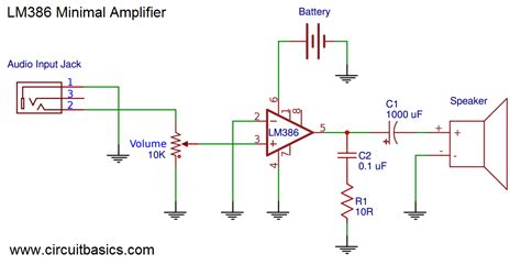
Basic LM386 Audio Amplifier Circuit
The basic LM386 audio amplifier circuit is straightforward and requires minimal external components. The following schematic represents a typical configuration:
Components Required
| Component | Value/Description |
|---|---|
| U1 | LM386N-1 Low Voltage Audio Power Amplifier |
| C1 | 10μF Electrolytic Capacitor |
| C2 | 220μF Electrolytic Capacitor |
| C3 | 0.05μF Ceramic Capacitor |
| C4 | 0.1μF Ceramic Capacitor |
| R1 | 10Ω Resistor |
| R2 | 10kΩ Potentiometer |
| Speaker | 8Ω Speaker |
In this basic configuration, the LM386 provides a voltage gain of 20 (26dB). The input signal is coupled to the non-inverting input (pin 3) through the 0.1μF capacitor C4. The 10kΩ potentiometer R2 serves as a volume control by adjusting the input signal level.
The 10μF capacitor C1 at the output (pin 5) helps to improve stability and prevent oscillations. The 220μF capacitor C2 is the bypass capacitor for the power supply, which helps to reduce noise and ripple. The 0.05μF capacitor C3 between pins 1 and 8 sets the internal gain of the amplifier to 20.

Modifying the LM386 Circuit for Different Amplification Functions
Increasing the Gain
To increase the gain of the Lm386 Amplifier, you can modify the basic circuit by adding a capacitor between pins 1 and 8. The value of this capacitor determines the gain of the amplifier, as shown in the table below:
| Capacitor Value | Voltage Gain |
|---|---|
| 0.05μF | 20 (26dB) |
| 0.005μF | 50 (34dB) |
| 0.0025μF | 100 (40dB) |
| No Capacitor | 200 (46dB) |
For example, to achieve a voltage gain of 50, you would replace the 0.05μF capacitor C3 with a 0.005μF capacitor.
Adding Bass Boost
You can enhance the bass response of the LM386 amplifier by adding a low-pass filter at the input stage. This can be achieved by modifying the input coupling capacitor C4 and adding a resistor in series with it. The following schematic shows the modified circuit:
In this configuration, the 0.1μF capacitor C4 is replaced with a 1μF capacitor, and a 15kΩ resistor R3 is added in series. The values of these components can be adjusted to fine-tune the bass response according to your preferences.
Implementing a Tone Control
To add tone control functionality to the LM386 amplifier, you can incorporate a simple passive tone control circuit at the input stage. The following schematic demonstrates this modification:
In this circuit, a dual-gang potentiometer RV1 (50kΩ) is used as the tone control. The treble control is achieved by the 4.7nF capacitor C5 in series with one section of the potentiometer, while the bass control is implemented by the 47nF capacitor C6 in series with the other section.
Adjusting the potentiometer will vary the amount of treble and bass frequencies in the output signal, allowing you to customize the tonal balance according to your liking.
Creating a Bridge-Tied Load (BTL) Configuration
For applications requiring higher output power, you can use two LM386 amplifiers in a bridge-tied load (BTL) configuration. In this arrangement, the outputs of the two amplifiers are connected in a push-pull manner, effectively doubling the output voltage swing and quadrupling the output power.
The following schematic illustrates the BTL configuration:
In this circuit, the input signal is split into two branches using a 10kΩ potentiometer RV1. One branch feeds the non-inverting input of the first LM386 (U1), while the other branch is inverted using a unity-gain inverting amplifier (U2A) and then fed to the non-inverting input of the second LM386 (U2).
The outputs of the two LM386 amplifiers are connected to the opposite ends of the speaker, resulting in a differential output signal. This configuration allows for higher output power and improved efficiency compared to a single LM386 amplifier.

Frequently Asked Questions (FAQ)
1. What is the maximum output power of the LM386 amplifier?
The LM386 can deliver up to 0.5W of output power into an 8Ω load when operating at a supply voltage of 6V. However, the actual output power may vary depending on the supply voltage, load impedance, and the specific configuration of the amplifier circuit.
2. Can I use the LM386 with a 4Ω speaker?
While the LM386 is designed to work with 8Ω loads, it is possible to use it with a 4Ω speaker. However, keep in mind that using a lower impedance load will result in higher current draw and may cause the amplifier to heat up more quickly. It is essential to ensure proper heat dissipation and not exceed the maximum power dissipation of the IC.
3. How can I reduce noise in my LM386 amplifier circuit?
To minimize noise in your LM386 amplifier circuit, consider the following tips:
- Use a regulated power supply with good filtering.
- Keep the input signal wires away from power supply and output wires to avoid crosstalk.
- Use proper grounding techniques and avoid ground loops.
- Add decoupling capacitors close to the power supply pins of the LM386.
- Use shielded cables for input signals if necessary.
4. Can I use the LM386 for stereo applications?
Yes, you can use two LM386 amplifiers to create a stereo amplifier circuit. Each amplifier will handle one channel (left or right). You can either use separate input signals for each channel or use a stereo potentiometer to split a single stereo input signal into left and right channels.
5. How can I make my LM386 amplifier more efficient?
To improve the efficiency of your LM386 amplifier, consider the following:
- Use a higher supply voltage (within the specified range) to reduce the current draw and increase output power.
- Use a properly matched speaker load (8Ω is recommended).
- Minimize the resistance in the speaker path by using thick wires and keeping the connections short.
- Use a BTL configuration for higher output power and improved efficiency.

Conclusion
The LM386 low voltage audio power amplifier is a versatile and easy-to-use IC that finds applications in various audio projects. By understanding its basic configuration and exploring different modification techniques, you can create custom amplifier circuits tailored to your specific needs.
From increasing the gain and adding bass boost to implementing tone controls and using a BTL configuration, the LM386 offers flexibility and room for experimentation. With its low cost and decent audio quality, the LM386 remains a popular choice among hobbyists and audio enthusiasts alike.
Remember to consider factors such as power supply filtering, proper grounding, and heat dissipation when designing your LM386 amplifier circuits. By following best practices and experimenting with different configurations, you can achieve the desired audio performance for your projects.
No responses yet