Introduction to the LM338 Adjustable Voltage Regulator
The LM338 is a three-terminal adjustable positive voltage regulator designed to supply more than 5A of load current with an output voltage adjustable over a 1.2V to 32V range. It offers several features that make it an attractive choice for power supply designs:
- Wide input voltage range: 1.2V to 40V
- Adjustable output voltage range: 1.2V to 32V
- High output current capability: >5A
- Internal thermal overload protection
- Internal short-circuit current limiting
- Available in TO-220 and TO-3 packages
LM338 Pin Configuration
The LM338 is available in both TO-220 and TO-3 packages. The pin configuration for the TO-220 package is as follows:
| Pin | Name | Description |
|---|---|---|
| 1 | ADJ | Output voltage adjustment pin |
| 2 | OUTPUT | Regulated output voltage pin |
| 3 | INPUT | Input voltage pin |
The TO-3 package has a similar pin configuration, with the ADJ pin connected to the case.
LM338 Datasheet Highlights
Let’s take a closer look at some of the key specifications and characteristics of the LM338, as provided in its datasheet.
Absolute Maximum Ratings
| Parameter | Value |
|---|---|
| Input Voltage | 40V |
| Power Dissipation | Internally Limited |
| Operating Junction Temperature Range | 0°C to 125°C |
| Storage Temperature Range | -65°C to 150°C |
Electrical Characteristics
| Parameter | Conditions | Min | Typ | Max |
|---|---|---|---|---|
| Reference Voltage | IOUT = 10mA, VIN-VOUT = 3V | 1.19V | 1.24V | 1.29V |
| Line Regulation | 3V ≤ (VIN-VOUT) ≤ 35V | 0.01%/V | ||
| Load Regulation | 10mA ≤ IOUT ≤ 5A | 0.1% | ||
| Minimum Load Current | VIN-VOUT = 35V | 3.5mA | 10mA | |
| Current Limit | VIN-VOUT = 10V | 6A | 8A |
Application Information
The LM338 can be used in various applications, including:
- Adjustable power supplies
- Battery Chargers
- Constant current regulators
- Programmable output voltage sources
The datasheet provides detailed information on the device’s operation, protection features, and application circuits.

Basic LM338 Adjustable Voltage Regulator Circuit
The most basic LM338 Circuit consists of the IC, two resistors (R1 and R2), and input and output capacitors (CIN and COUT). The output voltage is set by the ratio of R1 and R2, according to the following equation:
VOUT = 1.25V × (1 + R2 / R1) + IADJ × R2
where IADJ is the adjustment pin current, typically around 50μA.
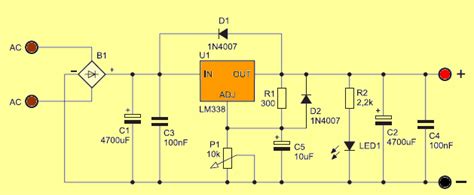
Here’s a schematic of the basic LM338 adjustable voltage regulator circuit:
To ensure stable operation, it is recommended to use a minimum output capacitance of 10μF and an input capacitance of 0.1μF. The capacitors should be placed close to the IC to minimize noise and improve transient response.

LM338 Application Circuits
The LM338 can be used in various application circuits to suit specific needs. Let’s explore a few common application circuits.
High Current Adjustable Voltage Regulator
To increase the output current capability of the LM338, multiple devices can be connected in parallel. Each device should have its own set of resistors (R1 and R2) to ensure proper current sharing. Here’s an example schematic of a high current adjustable voltage regulator using two LM338s:
In this configuration, the output voltage is set by the ratio of R1 and R2, just like in the basic circuit. The resistors R3 and R4 help balance the current between the two LM338s.
Constant Current Regulator
The LM338 can also be used as a constant current regulator by connecting a resistor (RSET) between the OUTPUT and ADJ pins. The regulated current is determined by the following equation:
IOUT = 1.25V / RSET
Here’s a schematic of an LM338-based constant current regulator:
In this circuit, the LED represents the load, and the current through it is regulated by the value of RSET.
Programmable Voltage Source
By using a potentiometer for R2 in the basic LM338 circuit, you can create a programmable voltage source. This allows for easy adjustment of the output voltage within the regulator’s range. Here’s a schematic of a programmable voltage source using the LM338:
In this circuit, the potentiometer (R2) is used to adjust the output voltage, while R1 sets the minimum output voltage when the potentiometer is at its minimum position.

Frequently Asked Questions (FAQ)
-
What is the maximum input voltage for the LM338?
The maximum input voltage for the LM338 is 40V, as specified in the datasheet’s absolute maximum ratings. -
How do I set the output voltage of the LM338?
The output voltage of the LM338 is set by the ratio of two external resistors, R1 and R2, connected to the ADJ pin. The output voltage can be calculated using the equation: VOUT = 1.25V × (1 + R2 / R1) + IADJ × R2. -
Can I connect multiple LM338s in parallel for higher output current?
Yes, you can connect multiple LM338s in parallel to increase the output current capability. Each device should have its own set of resistors (R1 and R2) to ensure proper current sharing. -
What is the purpose of the input and output capacitors in the LM338 circuit?
The input capacitor (CIN) helps to reduce noise and improve the transient response of the regulator, while the output capacitor (COUT) ensures stability and reduces output voltage ripple. It is recommended to use a minimum output capacitance of 10μF and an input capacitance of 0.1μF. -
Can the LM338 be used as a constant current regulator?
Yes, the LM338 can be configured as a constant current regulator by connecting a resistor (RSET) between the OUTPUT and ADJ pins. The regulated current is determined by the equation: IOUT = 1.25V / RSET.
Conclusion
The LM338 is a versatile adjustable voltage regulator that finds applications in various power supply designs, battery chargers, and constant current regulators. Its wide input and output voltage ranges, high output current capability, and protection features make it a popular choice among designers.
By understanding the LM338’s datasheet and exploring its application circuits, you can effectively utilize this IC in your projects. Remember to consider factors such as input and output capacitor selection, proper heat sinking for high current applications, and the use of appropriate resistor values to set the desired output voltage or current.
With its flexibility and robustness, the LM338 is a valuable tool in any electronics engineer’s arsenal, enabling the creation of stable, adjustable power supplies for a wide range of applications.
No responses yet