Introduction to LM324
The LM324 is a popular and versatile integrated circuit (IC) that consists of four independent, high-gain operational amplifiers (op-amps). This IC is widely used in various electronic applications, such as signal conditioning, filtering, and amplification. Its low cost, ease of use, and ability to operate with a single power supply make it an excellent choice for beginners and experienced engineers alike.
In this comprehensive guide, we will explore the fundamentals of the LM324 and provide practical examples of how to use it in different circuit configurations. By the end of this article, you will have a solid understanding of the LM324 and be able to design and build your own circuits using this powerful IC.
Key Features of the LM324
Before diving into circuit design, let’s take a closer look at the key features of the LM324:
- Four independent, high-gain op-amps in a single package
- Wide supply voltage range: 3V to 32V for single supply, ±1.5V to ±16V for dual supplies
- Low input bias current: 45nA (typical)
- High input voltage range: -0.3V to VCC-1.5V
- Output current up to 20mA per amplifier
- Unity-gain bandwidth: 1.2MHz
- Slew rate: 0.5V/μs
These features make the LM324 suitable for a wide range of applications, from low-frequency audio circuits to high-speed signal processing.

Pinout and Package
The LM324 is available in several package types, including DIP (Dual Inline Package), SOIC (Small Outline Integrated Circuit), and TSSOP (Thin Shrink Small Outline Package). The most common package is the 14-pin DIP, which has the following pinout:
| Pin | Function |
|---|---|
| 1 | Output 1 |
| 2 | Inverting Input 1 |
| 3 | Non-Inverting Input 1 |
| 4 | VCC- (Negative Supply) |
| 5 | Non-Inverting Input 2 |
| 6 | Inverting Input 2 |
| 7 | Output 2 |
| 8 | Output 3 |
| 9 | Inverting Input 3 |
| 10 | Non-Inverting Input 3 |
| 11 | VCC+ (Positive Supply) |
| 12 | Non-Inverting Input 4 |
| 13 | Inverting Input 4 |
| 14 | Output 4 |
It’s essential to understand the pinout when designing circuits with the LM324, as it will help you properly connect the inputs, outputs, and power supply.

Basic Op-Amp Configurations
Before exploring specific LM324 circuits, let’s review some basic op-amp configurations that form the foundation for more complex designs.
Inverting Amplifier
An inverting amplifier is a circuit that amplifies and inverts the input signal. The gain of the amplifier is determined by the ratio of the feedback resistor (Rf) to the input resistor (Rin):
Gain = -Rf/Rin
Here’s an example of an inverting amplifier using one of the LM324’s op-amps:
[Insert schematic of an LM324 inverting amplifier]
Non-Inverting Amplifier
A non-inverting amplifier amplifies the input signal without inverting it. The gain of the amplifier is determined by the ratio of the resistors in the feedback loop:
Gain = 1 + Rf/Rin
Here’s an example of a non-inverting amplifier using one of the LM324’s op-amps:
[Insert schematic of an LM324 non-inverting amplifier]
Voltage Follower (Buffer)
A voltage follower, also known as a buffer, is a circuit that provides a high-impedance input and a low-impedance output. It has a gain of 1, meaning the output voltage follows the input voltage. This configuration is useful for isolating stages and preventing loading effects.
Here’s an example of a voltage follower using one of the LM324’s op-amps:
[Insert schematic of an LM324 voltage follower]

LM324 Circuit Examples
Now that we’ve covered the basics, let’s explore some practical LM324 circuit examples.
Audio Preamplifier
An audio preamplifier is a circuit that amplifies low-level audio signals from sources like microphones or guitar pickups. Here’s an example of a simple audio preamplifier using the LM324:
[Insert schematic of an LM324 audio preamplifier]
In this circuit, the first op-amp is configured as a non-inverting amplifier with a gain of 11, while the second op-amp is a voltage follower that provides a low-impedance output. The 10kΩ potentiometer allows for adjusting the gain, and the capacitors help filter out unwanted noise and DC offset.
Low-Pass Filter
A low-pass filter is a circuit that attenuates high-frequency signals while allowing low-frequency signals to pass through. Here’s an example of a second-order low-pass filter using the LM324:
[Insert schematic of an LM324 low-pass filter]
This circuit uses two op-amps in a Sallen-Key topology to create a second-order filter. The cutoff frequency and damping factor are determined by the values of the resistors and capacitors. You can use online calculators or design tools to determine the appropriate component values for your desired cutoff frequency.
Precision Rectifier
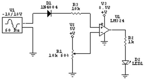
A precision rectifier is a circuit that converts an AC signal into a DC signal while maintaining the input waveform’s shape. Here’s an example of a precision rectifier using two of the LM324’s op-amps:
[Insert schematic of an LM324 precision rectifier]
In this circuit, the first op-amp is configured as a voltage follower, while the second op-amp and the diodes form a full-wave rectifier. The 10kΩ potentiometer allows for adjusting the output level.
Schmitt Trigger
A Schmitt trigger is a circuit that converts a slowly varying input signal into a clean, sharp output signal. It has two threshold voltages, one for the rising edge and one for the falling edge, which helps to reduce the effects of noise and hysteresis. Here’s an example of a Schmitt trigger using one of the LM324’s op-amps:
[Insert schematic of an LM324 Schmitt trigger]
The threshold voltages are determined by the ratio of the resistors in the voltage divider network. The output of the Schmitt trigger will be high when the input voltage is above the upper threshold and low when the input voltage is below the lower threshold.
Tips for Working with the LM324
To ensure the best performance and reliability when working with the LM324, consider the following tips:
- Always ensure proper power supply decoupling by placing ceramic capacitors (0.1μF to 1μF) close to the IC’s power pins.
- Be mindful of the op-amp’s input and output voltage limits to avoid saturation and distortion.
- Use appropriate resistor and capacitor values to achieve the desired gain, frequency response, and stability in your circuits.
- Consider using a heat sink when operating the LM324 at high temperatures or when driving heavy loads.
- When designing circuits with multiple op-amps, be aware of potential crosstalk and interaction between the different stages.
Frequently Asked Questions (FAQ)
-
Q: Can the LM324 be used with a single power supply?
A: Yes, the LM324 can operate with a single power supply ranging from 3V to 32V. -
Q: What is the maximum output current of the LM324?
A: Each op-amp in the LM324 can provide up to 20mA of output current. -
Q: How do I determine the appropriate gain for my LM324 amplifier circuit?
A: The gain of an LM324 amplifier is determined by the ratio of the resistors in the feedback network. For an inverting amplifier, the gain is -Rf/Rin, while for a non-inverting amplifier, the gain is 1 + Rf/Rin. -
Q: Can I use the LM324 for high-frequency applications?
A: The LM324 has a unity-gain bandwidth of 1.2MHz, which makes it suitable for low to medium-frequency applications. For high-frequency applications, consider using op-amps with higher bandwidth, such as the LM358 or LM318. -
Q: How do I prevent oscillations and instability in my LM324 circuits?
A: To prevent oscillations and instability, ensure proper power supply decoupling, use appropriate compensation techniques (e.g., feedback capacitors), and be mindful of the op-amp’s input and output voltage limits. Additionally, consider using a small capacitor (a few picofarads) between the op-amp’s output and inverting input to provide high-frequency feedback compensation.
Conclusion
The LM324 is a versatile and widely used quad op-amp IC that offers a wide range of applications in analog circuit design. By understanding its key features, pinout, and basic op-amp configurations, you can create a variety of circuits, including amplifiers, filters, rectifiers, and Schmitt triggers.
Remember to follow best practices when working with the LM324, such as ensuring proper power supply decoupling, using appropriate component values, and being mindful of the op-amp’s limitations. With the knowledge gained from this guide, you’ll be well-equipped to design and build your own LM324 circuits for your projects.
As you continue to explore the world of analog electronics, keep experimenting with different circuit configurations and applications using the LM324. With its flexibility and ease of use, this IC will undoubtedly become a valuable tool in your electronics toolbox.
No responses yet