Introduction to Laser Diodes and Their Applications
Laser diodes are a type of semiconductor device that emits coherent light when an electrical current is passed through them. They are widely used in various applications, including fiber-optic communication, barcode scanners, laser pointers, and optical storage devices. Compared to other types of lasers, laser diodes are compact, efficient, and cost-effective, making them an attractive choice for many applications.
How Laser Diodes Work
A laser diode consists of a p-n junction, similar to a regular diode, but with a special structure that allows it to emit coherent light. When a forward bias voltage is applied to the laser diode, electrons and holes recombine in the active region, releasing energy in the form of photons. The wavelength of the emitted light depends on the bandgap of the semiconductor material used in the laser diode.
The structure of a laser diode includes:
- Active region: The area where light emission occurs
- Cladding layers: Layers surrounding the active region that confine the light
- Facets: Cleaved or polished ends of the laser diode that act as mirrors, forming an optical cavity
Types of Laser Diodes
There are several types of laser diodes, each with unique characteristics and applications:
- Fabry-Perot (FP) laser diodes: These have a simple structure and emit light over a relatively broad spectrum.
- Distributed Feedback (DFB) laser diodes: These have a grating structure that provides wavelength selectivity and single-mode operation.
- Vertical Cavity Surface Emitting Lasers (VCSELs): These emit light perpendicular to the surface of the wafer and have a circular beam profile.
- Quantum Cascade Lasers (QCLs): These emit light in the mid-infrared to terahertz range and are based on intersubband transitions in quantum wells.
Laser Diode Characteristics and Requirements
To effectively drive a laser diode, it is essential to understand its characteristics and requirements. This section will discuss the key parameters and considerations for designing a Laser diode driver circuit.
Optical Power and Forward Current
The optical output power of a laser diode is directly related to the forward current flowing through the device. However, the relationship between current and optical power is not linear. Laser diodes have a threshold current (Ith) below which the device acts as an LED, emitting incoherent light. Above the threshold current, the optical power increases linearly with the current.
The slope of the linear region is called the slope efficiency (ηs) and is expressed in units of W/A. The optical power (Po) can be calculated using the following equation:
Po = ηs × (If – Ith)
where If is the forward current.
Forward Voltage and Series Resistance
Laser diodes have a forward voltage drop (Vf) that depends on the semiconductor material and the device structure. Typical values range from 1.5 V to 4 V. The forward voltage also varies with temperature, increasing as the temperature decreases.
In addition to the forward voltage, laser diodes have a series resistance (Rs) that contributes to the total voltage drop across the device. The series resistance is typically in the range of a few ohms.
Temperature Dependence and Thermal Management
Laser diodes are sensitive to temperature changes, which can affect their performance and reliability. As the temperature increases, the threshold current increases, and the slope efficiency decreases. This leads to a reduction in optical output power for a given forward current.
To maintain stable operation and prevent damage, laser diodes require proper thermal management. This can be achieved through the use of heatsinks, thermoelectric coolers (TECs), or active temperature control systems.
Electrical and Optical Noise
Laser diodes are subject to various sources of electrical and optical noise, which can degrade the signal quality and limit the achievable signal-to-noise ratio (SNR). The main types of noise include:
- Shot noise: Caused by the discrete nature of electron flow and photon emission
- Thermal noise: Generated by the random motion of charge carriers in the device
- Relative Intensity Noise (RIN): Fluctuations in the optical output power due to spontaneous emission and other factors
To minimize the impact of noise, laser diode driver circuits must be designed with low-noise components and proper shielding techniques.
Laser Diode Driver Circuit Design Considerations
Designing a laser diode driver circuit requires careful consideration of several factors to ensure safe, efficient, and reliable operation. This section will discuss the key design considerations and provide guidance on selecting appropriate components and topologies.
Current Regulation and Stability
Laser diodes are current-driven devices, meaning that their optical output power is directly related to the forward current. To maintain stable operation and prevent damage, the driver circuit must provide precise current regulation and protection against overcurrent conditions.
The most common approach to current regulation is to use a constant current source. This can be implemented using a variety of topologies, such as:
- Linear regulators: Simple and low-noise, but inefficient and limited in output current
- Switching regulators: Efficient and capable of high output currents, but more complex and potentially noisy
- Current mirrors: Provide accurate current scaling and can be used in conjunction with other regulator topologies
When designing a current regulator, it is essential to consider factors such as load regulation, line regulation, and transient response to ensure stable operation under varying conditions.
Protection Circuitry
Laser diodes are sensitive devices that can be easily damaged by excessive current, voltage, or temperature. To prevent damage and ensure long-term reliability, the driver circuit must incorporate appropriate protection mechanisms.
Some common protection features include:
- Overcurrent protection: Limits the maximum current to a safe level, typically using a current-limiting resistor or a foldback circuit
- Reverse voltage protection: Prevents damage from reverse bias voltages, using a series diode or a protection IC
- Electrostatic Discharge (ESD) protection: Suppresses voltage spikes and transients, using ESD diodes or transient voltage suppressors (TVS)
- Thermal shutdown: Disables the laser diode if the temperature exceeds a safe limit, using a temperature sensor and a comparator circuit
By incorporating these protection mechanisms, the laser diode driver circuit can ensure safe operation and prevent costly damage to the laser diode.
Modulation and Control
In many applications, it is necessary to modulate the optical output of the laser diode to transmit information or control the beam intensity. The driver circuit must be designed to support the required Modulation Techniques and provide appropriate control signals.
Common modulation techniques for laser diodes include:
- Direct modulation: The forward current is modulated directly, which changes the optical output power
- External modulation: The laser diode is operated in continuous wave (CW) mode, and an external modulator (e.g., electro-optic modulator) is used to modulate the beam
- Pulse width modulation (PWM): The laser diode is switched on and off rapidly, with the duty cycle controlling the average optical power
The driver circuit must be able to handle the required modulation bandwidth and provide clean, fast transitions between states. This may involve the use of high-speed op-amps, transistors, or dedicated laser driver ICs.
Power Supply and Noise Reduction
The power supply for the laser diode driver circuit must be carefully designed to provide clean, stable power and minimize noise. Noise on the power supply can couple into the laser diode, leading to fluctuations in the optical output and degrading the signal quality.
To reduce power supply noise, consider the following techniques:
- Use low-noise linear regulators or switching regulators with appropriate filtering
- Decouple the power supply using ceramic capacitors close to the laser diode and driver IC
- Use separate power supplies or voltage regulators for analog and digital sections of the circuit
- Implement proper grounding techniques, such as star grounding or ground plane
By minimizing power supply noise, the laser diode driver circuit can achieve better signal integrity and reliability.

Laser Diode Driver Circuit Topologies
There are several common laser diode driver circuit topologies, each with its own advantages and disadvantages. This section will discuss some of the most popular topologies and provide examples of their implementation.
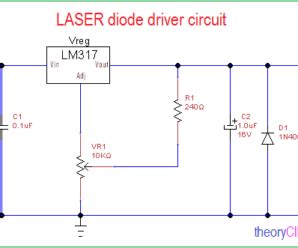
Linear Regulator-Based Driver
A linear regulator-based laser diode driver uses a voltage regulator (e.g., LM317) to provide a constant current to the laser diode. The current is set by a resistor connected between the adjust pin and the output of the regulator.
Advantages:
– Simple and low-cost design
– Low noise and ripple
– Easy to implement current limiting and protection features
Disadvantages:
– Inefficient, especially for high-power laser diodes
– Limited output current range
– Requires a heatsink for the regulator
Example circuit:
           +V
            |
           +-+
           | |
           | |  LM317
           | |
           +-+
            |
            +---+---+
            |   |   |
            |   |   +---> Laser Diode Anode
            |   |
           R1  R2
            |   |
            |   +-------> Laser Diode Cathode
            |
           GND
In this circuit, R1 and R2 set the output current according to the equation:
Iout = 1.25 V / R1
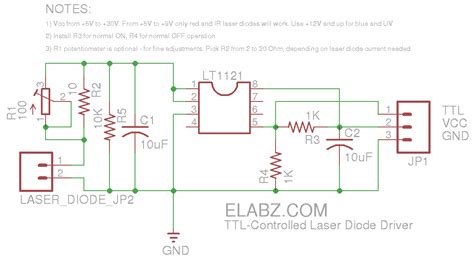
Switching Regulator-Based Driver
A switching regulator-based laser diode driver uses a DC-DC converter (e.g., buck converter) to provide a constant current to the laser diode. The switching regulator efficiently steps down the input voltage and provides current regulation through a feedback loop.
Advantages:
– High efficiency, especially for high-power laser diodes
– Wide output current range
– Compact design, as heatsinks are often not required
Disadvantages:
– More complex design compared to linear regulators
– Higher noise and ripple due to switching action
– Requires careful layout and filtering to minimize EMI
Example circuit:
           +V
            |
           +-+
           | |
           | |  Buck Converter
           | |
           +-+
            |
            +---+---+
            |   |   |
            |   |   +---> Laser Diode Anode
            |   |
           L1  C1
            |   |
            |   +-------> Laser Diode Cathode
            |
           GND
In this circuit, the buck converter steps down the input voltage and provides current regulation through a feedback loop that monitors the current through a sense resistor.
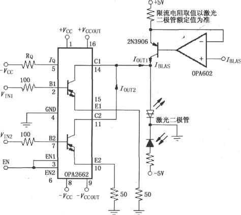
Constant Current Source-Based Driver
A constant current source-based laser diode driver uses a transistor (e.g., BJT or MOSFET) and an op-amp to provide a constant current to the laser diode. The op-amp compares the voltage across a sense resistor with a reference voltage and adjusts the transistor’s base or gate voltage to maintain a constant current.
Advantages:
– Accurate current regulation
– Adjustable output current
– Can be designed for high output currents
Disadvantages:
– Requires a stable reference voltage
– Op-amp selection is critical for noise performance and bandwidth
– May require additional protection circuitry
Example circuit:
           +V
            |
           +-+
           | |
           | |  Op-Amp
           | |
           +-+
            |
            +---+---+
            |   |   |
            |   |   +---> Laser Diode Anode
            |   |
           R1  Q1
            |   |
            +---+-------> Laser Diode Cathode
            |
           GND
In this circuit, the op-amp compares the voltage across R1 with a reference voltage and adjusts the base voltage of Q1 to maintain a constant current through the laser diode.
Practical Implementation and Testing
Once the laser diode driver circuit has been designed, it is essential to implement and test it properly to ensure safe and reliable operation. This section will discuss some practical considerations and provide guidance on testing and troubleshooting.
PCB Layout and Component Selection
Proper PCB layout and component selection are critical for the performance and reliability of the laser diode driver circuit. Consider the following guidelines:
- Use a ground plane to provide a low-impedance return path and minimize ground loops
- Keep the high-current paths short and wide to reduce resistance and inductance
- Locate decoupling capacitors close to the laser diode and driver IC to suppress high-frequency noise
- Use shielded cables or twisted pairs for sensitive signals to reduce EMI
- Select components with appropriate ratings for the expected operating conditions (e.g., voltage, current, temperature)
By following these guidelines, the laser diode driver circuit can achieve better performance and reliability.
Testing and Characterization
Before using the laser diode driver circuit in an application, it is essential to test and characterize its performance. This involves measuring key parameters such as output current, voltage, noise, and stability.
Some common testing methods include:
- Current measurement: Use a high-precision current probe or a current-sense resistor to measure the output current
- Voltage measurement: Use a digital multimeter or oscilloscope to measure the voltage across the laser diode and driver circuit
- Noise measurement: Use a spectrum analyzer or a high-bandwidth oscilloscope to measure the noise spectrum and RMS noise level
- Stability testing: Vary the input voltage, load, and temperature to ensure stable operation under different conditions
By thoroughly testing and characterizing the laser diode driver circuit, potential issues can be identified and addressed before deployment.
Troubleshooting and Debugging
If the laser diode driver circuit does not perform as expected, it may be necessary to troubleshoot and debug the design. Some common issues and their potential causes include:
- No output: Check for open circuits, short circuits, or damaged components
- Unstable output: Check for oscillations, insufficient decoupling, or poor grounding
- High noise: Check for EMI sources, ground loops, or improper shielding
- Overheating: Check for excessive current draw, insufficient heatsinking, or poor thermal management
To troubleshoot the circuit, use a systematic approach:
- Verify the power supply voltage and current
- Check the component values and connections
- Use a multimeter or oscilloscope to probe test points and trace signals
- Compare the measured waveforms with the expected ones based on simulations or calculations
By following a structured troubleshooting process, the root cause of the issue can be identified and addressed.
Frequently Asked Questions (FAQ)
- What is the difference between a laser diode and an LED?
Laser diodes emit coherent, monochromatic light through stimulated emission, while LEDs emit incoherent, broadband light through spontaneous emission. Laser diodes also have a much higher output power and directionality compared to LEDs. - Can I use a regular DC power supply to drive a laser diode?
No, laser diodes require a constant current source with precise regulation and protection features. Using a regular DC power supply can lead to damage or unstable operation of the laser diode. - How do I select the appropriate laser diode driver topology for my application?
The choice of laser diode driver topology depends on factors such as the required output power, efficiency, noise performance, and cost. Linear regulators are simple and low-noise but inefficient, while switching regulators are efficient but more complex. Constant current sources offer accurate regulation but may require additional protection circuitry. - What should I do if my laser diode driver circuit is not working properly?
If the laser diode driver circuit is not working as expected, follow a systematic troubleshooting approach. Check the power supply, component values, and connections. Use a multimeter or oscilloscope to probe test points and compare the measured waveforms with the expected ones. If the issue persists, consult the manufacturer’s documentation or seek assistance from an experienced engineer. - How can I ensure the long-term reliability of my laser diode and driver circuit?
To ensure the long-term reliability of the laser diode and driver circuit, follow best practices for design, implementation, and testing. This includes selecting appropriate components, designing for proper thermal management, incorporating protection features, and thoroughly testing the circuit under various operating conditions. Regular maintenance and monitoring can also help identify potential issues before they lead to failure.
Conclusion
In this article, we have provided a comprehensive beginner’s guide to laser diode driver circuits. We have discussed the fundamentals of laser diodes, their characteristics, and the requirements for driving them safely and efficiently.
We have also explored various laser diode driver circuit topologies, including linear regulators, switching regulators, and constant current sources. Each topology has its own advantages and disadvantages, and the choice depends on the specific application requirements.
Practical implementation and testing are critical for the success of any laser diode driver circuit. Proper PCB layout, component selection, and testing techniques can help ensure reliable and stable operation.
By understanding the principles and best practices outlined in this guide, engineers and hobbyists can design and implement laser diode driver circuits for a wide range of applications, from optical communication to material processing.
As the demand for laser-based technologies continues to grow, the importance of robust and efficient laser diode driver circuits will only
No responses yet