Introduction to IR Detector Circuits
An infrared (IR) detector circuit is a fundamental electronic device that detects the presence of infrared radiation in its vicinity. IR detectors are widely used in various applications, such as remote control systems, motion detection, temperature sensing, and obstacle avoidance. In this comprehensive guide, we will delve into the world of IR detector circuits, discussing their working principles, components, and step-by-step instructions on how to build your own IR detector circuit.
Understanding Infrared Radiation
Before we dive into the details of IR detector circuits, let’s briefly understand what infrared radiation is. Infrared radiation is a type of electromagnetic radiation with wavelengths longer than visible light but shorter than microwaves. It is invisible to the human eye but can be detected by electronic sensors.
Infrared radiation is emitted by all objects with a temperature above absolute zero. The amount and wavelength of the emitted radiation depend on the object’s temperature. This property makes infrared radiation useful for detecting the presence and movement of objects, as well as measuring their temperature.
Types of IR Detectors
IR detectors can be broadly classified into two categories: thermal detectors and photon detectors.
-
Thermal Detectors: Thermal detectors work by measuring the temperature change caused by the absorption of infrared radiation. They are relatively slow in response but can detect a wide range of wavelengths. Examples of thermal detectors include thermocouples, thermopiles, and bolometers.
-
Photon Detectors: Photon detectors, also known as quantum detectors, work by directly converting the absorbed infrared photons into electrical signals. They are faster and more sensitive than thermal detectors but are limited to specific wavelength ranges. Examples of photon detectors include photodiodes and phototransistors.
In this guide, we will focus on building an IR detector circuit using a photon detector, specifically an IR photodiode.
Components Required for IR Detector Circuit
To build an IR detector circuit, you will need the following components:
- IR Photodiode (e.g., BPW34, SFH213)
- Operational Amplifier (e.g., LM358, TL072)
- Resistors (values will be specified in the circuit diagram)
- Capacitors (values will be specified in the circuit diagram)
- Potentiometer (for adjusting sensitivity)
- LED (for visual indication)
- Breadboard
- Connecting wires
- Power supply (e.g., 9V battery)
IR Photodiode
An IR photodiode is a semiconductor device that converts infrared light into an electrical current. When infrared radiation falls on the photodiode, it generates a small current proportional to the intensity of the radiation. The photodiode is the heart of the IR detector circuit, as it senses the presence of infrared radiation.
Operational Amplifier
An operational amplifier (op-amp) is an electronic device that amplifies the weak current generated by the IR photodiode. It also serves as a comparator, comparing the amplified signal with a reference voltage to determine the presence or absence of infrared radiation.
Resistors and Capacitors
Resistors and capacitors are passive components used to control the flow of current and filter out noise in the circuit. They help in setting the gain, bandwidth, and stability of the op-amp.
Potentiometer
A potentiometer is a variable resistor that allows you to adjust the sensitivity of the IR detector circuit. By changing the resistance of the potentiometer, you can fine-tune the circuit to detect infrared radiation at different distances and intensities.
LED
An LED (Light Emitting Diode) is used as a visual indicator to show the presence of infrared radiation. When the IR detector circuit detects infrared radiation, the LED will turn on, providing a visual confirmation.

Building the IR Detector Circuit
Now that we have discussed the components required, let’s proceed with the step-by-step instructions on how to build the IR detector circuit.
Step 1: Assemble the Components
- Place the breadboard on a flat surface.
- Insert the IR photodiode into the breadboard, ensuring that the cathode (shorter lead) is connected to the ground rail and the anode (longer lead) is connected to a separate row.
- Insert the op-amp (e.g., LM358) into the breadboard, following the pinout diagram provided in the datasheet.
- Place the resistors and capacitors in the appropriate positions according to the circuit diagram (provided below).
- Connect the potentiometer to the breadboard, with the middle pin connected to a separate row and the outer pins connected to the power supply and ground rails, respectively.
- Insert the LED into the breadboard, with the cathode (shorter lead) connected to the ground rail and the anode (longer lead) connected to a separate row.
Step 2: Connect the Power Supply
- Connect the positive terminal of the power supply (e.g., 9V battery) to the power rail on the breadboard.
- Connect the negative terminal of the power supply to the ground rail on the breadboard.
Step 3: Wire the Circuit
- Connect the anode of the IR photodiode to the non-inverting input (pin 3) of the op-amp.
- Connect a resistor (e.g., 1MΩ) between the non-inverting input and ground to provide a path for the bias current.
- Connect the inverting input (pin 2) of the op-amp to the wiper (middle pin) of the potentiometer.
- Connect a resistor (e.g., 10kΩ) between the inverting input and the output (pin 1) of the op-amp to set the gain.
- Connect a capacitor (e.g., 0.1μF) between the non-inverting input and ground to filter out high-frequency noise.
- Connect the anode of the LED to the output of the op-amp through a current-limiting resistor (e.g., 1kΩ).
Step 4: Adjust the Sensitivity
- Turn the potentiometer to adjust the sensitivity of the IR detector circuit. Rotating the potentiometer clockwise will increase the sensitivity, while rotating it counterclockwise will decrease the sensitivity.
- Test the circuit by pointing an IR remote control towards the IR photodiode and pressing any button. The LED should light up when infrared radiation is detected.
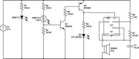
Circuit Diagram
Here is a simplified circuit diagram of the IR detector circuit:
           +9V
            |
            |
           ___
          |   |
          | P |
          |___|
            |
            |
            |
            |
           ___
IR       |   |
Photodiode   |
Anode    |   |
---------|   |
         |   |
         |   |
          ___
           |
           |
           |
           |
          ___
         |   |
         |   |
         |   |
LED      |   |
Anode    |___|
            |
            |
           GND

Testing and Troubleshooting
Once you have assembled the IR detector circuit, it’s time to test its functionality and troubleshoot any issues that may arise.
Testing the Circuit
- Power on the circuit by connecting the power supply (e.g., 9V battery).
- Point an IR remote control towards the IR photodiode.
- Press any button on the remote control.
- Observe the LED. It should light up when infrared radiation is detected.
- Adjust the sensitivity of the circuit using the potentiometer if necessary. Rotate the potentiometer clockwise to increase sensitivity and counterclockwise to decrease sensitivity.
- Test the circuit at different distances and angles to ensure proper operation.
Troubleshooting Tips
If the IR detector circuit is not functioning as expected, consider the following troubleshooting tips:
-
Check the power supply: Ensure that the power supply is properly connected and providing the correct voltage (e.g., 9V). Use a multimeter to verify the voltage.
-
Verify component connections: Double-check all the connections in the circuit, ensuring that the components are properly inserted into the breadboard and the wires are connected to the correct pins.
-
Inspect the IR photodiode: Make sure that the IR photodiode is properly oriented, with the anode connected to the non-inverting input of the op-amp and the cathode connected to ground.
-
Check the op-amp: Verify that the op-amp is functioning correctly by measuring the voltage at its output pin. If the output voltage is not changing when infrared radiation is present, the op-amp may be faulty.
-
Adjust the sensitivity: If the circuit is not detecting infrared radiation or is too sensitive, adjust the potentiometer to fine-tune the sensitivity. Rotate the potentiometer clockwise to increase sensitivity and counterclockwise to decrease sensitivity.
-
Replace components: If the circuit still does not work after checking the connections and adjusting the sensitivity, try replacing the components one by one, starting with the IR photodiode and op-amp.

Applications of IR Detector Circuits
IR detector circuits have a wide range of applications in various fields. Some of the common applications include:
-
Remote Control Systems: IR detector circuits are extensively used in remote control systems for televisions, air conditioners, and other electronic devices. The IR detector in the device receives the infrared signals from the remote control and decodes them to perform the desired actions.
-
Motion Detection: IR detector circuits can be used for motion detection in security systems, automatic doors, and lighting control. When an object or person moves within the detection range of the IR detector, it triggers an alarm or activates the corresponding device.
-
Obstacle Avoidance: IR detector circuits are employed in robotics and autonomous vehicles for obstacle avoidance. The IR detectors help the robot or vehicle detect obstacles in its path and navigate around them.
-
Temperature Sensing: IR detectors can be used for non-contact temperature measurement. By measuring the infrared radiation emitted by an object, the temperature can be determined without physically touching the object.
-
Flame Detection: IR detector circuits are used in fire alarm systems to detect the presence of flames. The infrared radiation emitted by flames is detected by the IR detector, triggering the alarm.
-
Heart Rate Monitoring: IR detectors can be used in wearable devices to monitor heart rate. The IR detector measures the changes in blood flow caused by the pulse, allowing for non-invasive heart rate monitoring.
FAQs
-
What is the range of an IR detector circuit?
The range of an IR detector circuit depends on several factors, such as the type of IR photodiode used, the sensitivity of the circuit, and the intensity of the infrared radiation source. Typically, IR detector circuits can detect infrared radiation from a few centimeters to several meters, depending on the application. -
Can IR detectors detect visible light?
No, IR detectors are specifically designed to detect infrared radiation, which is outside the visible light spectrum. They are not sensitive to visible light, making them suitable for applications where ambient light interference needs to be minimized. -
How can I increase the range of my IR detector circuit?
To increase the range of your IR detector circuit, you can try the following: - Use a more sensitive IR photodiode.
- Increase the gain of the op-amp by adjusting the feedback resistor.
- Use a higher intensity infrared radiation source.
-
Use a reflector or lens to focus the infrared radiation onto the photodiode.
-
Can I use an IR detector circuit for outdoor applications?
Yes, IR detector circuits can be used for outdoor applications, but there are a few considerations to keep in mind: - Outdoor environments may have higher levels of ambient infrared radiation from sunlight, which can interfere with the IR detector’s performance.
- Temperature changes and humidity can affect the sensitivity of the IR detector.
-
Proper weatherproofing and enclosure design are necessary to protect the circuit from the elements.
-
What is the difference between an IR detector and an IR emitter?
An IR detector is a device that detects the presence of infrared radiation, while an IR emitter is a device that emits infrared radiation. IR detectors are used to sense the infrared radiation emitted by objects or IR emitters. IR emitters, such as IR LEDs, are commonly used in remote control systems to transmit infrared signals to the IR detector in the receiving device.
Conclusion
In this comprehensive guide, we have explored the world of IR detector circuits, discussing their working principles, components, and step-by-step instructions on how to build your own IR detector circuit. We have also covered testing and troubleshooting tips, as well as various applications of IR detector circuits.
IR detector circuits are versatile and widely used in numerous fields, from remote control systems and motion detection to temperature sensing and flame detection. By understanding the basics of IR detectors and building your own circuit, you can explore the fascinating world of infrared radiation and its applications.
Remember to follow the circuit diagram carefully, use appropriate components, and take necessary precautions while handling electronic devices. With practice and experimentation, you can enhance your skills in building and customizing IR detector circuits for various projects.
We hope this guide has been informative and helpful in your journey of building IR detector circuits. Happy experimenting!
No responses yet