Introduction to IC7447
The IC7447 is a BCD-to-Seven-Segment Decoder/Driver integrated circuit that is widely used in electronic displays. It is designed to convert a Binary Coded Decimal (BCD) input into a seven-segment display output, making it easier to display numeric values on LED or LCD displays. This guide will provide a comprehensive introduction to the IC7447, its features, applications, and how to use it effectively in your electronic projects.
What is a BCD-to-Seven-Segment Decoder/Driver?
A BCD-to-Seven-Segment Decoder/Driver is an electronic component that takes a BCD input and converts it into the appropriate signals to drive a seven-segment display. BCD is a digital encoding system where each decimal digit is represented by a four-bit binary code. The IC7447 accepts this four-bit BCD input and outputs the corresponding signals to illuminate the appropriate segments of a seven-segment display, allowing it to display the decimal digit.
Features of the IC7447
The IC7447 offers several key features that make it a popular choice for electronic display applications:
- BCD Input: The IC7447 accepts a four-bit BCD input, allowing it to decode decimal digits from 0 to 9.
- Seven-Segment Output: It provides seven output pins that directly drive the segments of a seven-segment display, eliminating the need for additional circuitry.
- Active-Low Output: The output pins of the IC7447 are active-low, meaning that a logic ‘0’ on an output pin will illuminate the corresponding segment on the display.
- Ripple Blanking Input: The IC7447 includes a ripple blanking input pin (RBI) that allows you to disable the display when not in use, saving power and increasing the lifespan of the display.
- Lamp Test Input: The lamp test input pin (LT) enables you to test the functionality of all segments on the display simultaneously.
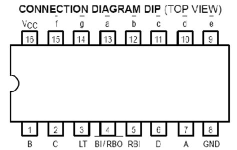
Understanding the IC7447 Pinout
To effectively use the IC7447 in your projects, it’s essential to understand its pinout and the function of each pin. The IC7447 is available in a 16-pin DIP (Dual Inline Package) format. Here’s a table outlining the pinout:
| Pin Number | Pin Name | Description |
|---|---|---|
| 1 | B | BCD Input B |
| 2 | C | BCD Input C |
| 3 | LT | Lamp Test Input |
| 4 | RBI | Ripple Blanking Input |
| 5 | RBO | Ripple Blanking Output |
| 6 | D | BCD Input D |
| 7 | A | BCD Input A |
| 8 | GND | Ground |
| 9 | e | Segment e Output |
| 10 | d | Segment d Output |
| 11 | c | Segment c Output |
| 12 | b | Segment b Output |
| 13 | a | Segment a Output |
| 14 | f | Segment f Output |
| 15 | g | Segment g Output |
| 16 | VCC | Power Supply |
BCD Inputs (A, B, C, D)
The BCD inputs A, B, C, and D are used to provide the four-bit BCD value to the IC7447. The combination of these inputs determines which decimal digit (0-9) will be displayed on the seven-segment display. The truth table below shows the relationship between the BCD inputs and the corresponding decimal digit:
| BCD Input (DCBA) | Decimal Digit |
|---|---|
| 0000 | 0 |
| 0001 | 1 |
| 0010 | 2 |
| 0011 | 3 |
| 0100 | 4 |
| 0101 | 5 |
| 0110 | 6 |
| 0111 | 7 |
| 1000 | 8 |
| 1001 | 9 |
Seven-Segment Outputs (a, b, c, d, e, f, g)
The seven-segment outputs (a, b, c, d, e, f, g) are used to drive the individual segments of a seven-segment display. Each output corresponds to a specific segment, as shown in the diagram below:
   a
f     b
   g
e     c
   d
When an output pin is driven low (logic ‘0’), the corresponding segment on the display will illuminate. The IC7447 internally decodes the BCD input and sets the appropriate output pins low to display the corresponding decimal digit.
Ripple Blanking Input (RBI) and Output (RBO)
The Ripple Blanking Input (RBI) is used to disable the display when not in use. When the RBI pin is held high (logic ‘1’), the display will be blanked, meaning all segments will be turned off. This feature is useful for saving power and increasing the lifespan of the display.
The Ripple Blanking Output (RBO) is an open-collector output that can be used to cascade multiple IC7447s for displaying multi-digit numbers. When the RBI pin is held high, the RBO pin will also go high, allowing you to connect it to the RBI pin of the next IC7447 in the chain.
Lamp Test Input (LT)
The Lamp Test Input (LT) is used to test the functionality of all segments on the display simultaneously. When the LT pin is held low (logic ‘0’), all segments will illuminate, regardless of the BCD input. This feature is useful for verifying that all segments are working correctly and for troubleshooting any issues with the display.

Interfacing the IC7447 with a Seven-Segment Display
To use the IC7447 with a seven-segment display, you need to connect the appropriate pins of the IC to the corresponding segments of the display. Here’s a step-by-step guide on how to interface the IC7447 with a common cathode seven-segment display:
- Connect the VCC pin of the IC7447 to the positive power supply (usually 5V).
- Connect the GND pin of the IC7447 to the ground of your circuit.
- Connect the BCD input pins (A, B, C, D) of the IC7447 to the appropriate output pins of your microcontroller or BCD source.
- Connect the seven-segment output pins (a, b, c, d, e, f, g) of the IC7447 to the corresponding segments of your seven-segment display.
- Connect the common cathode pin of the seven-segment display to ground.
- If you want to use the ripple blanking feature, connect the RBI pin to the appropriate control signal. If not, connect the RBI pin to ground.
- If you want to use the lamp test feature, connect the LT pin to the appropriate control signal. If not, connect the LT pin to VCC.
Here’s a schematic diagram illustrating the connections:
         IC7447
   +--------------+
   |              |
   |    VCC   GND |
   |     |     |  |
   |   A |     |  |
   |   B |     |  |
   |   C |     |  |
   |   D |     |  |
   |     |     |  |
   |  RBI|     |  |
   |  RBO|     |  |
   |   LT|     |  |
   |     |     |  |
   |     a     e  |
   |     b     d  |
   |     c     DP |
   |     d     c  |
   |     e     b  |
   |     f     a  |
   |     g     f  |
   |              |
   +--------------+
         |||||||||
         |||||||||
    Seven-Segment Display
By following these connections, you can successfully interface the IC7447 with a seven-segment display and control the displayed digit using the BCD inputs.

Example Circuit: Displaying a Count from 0 to 9
To demonstrate the usage of the IC7447, let’s create a simple circuit that displays a count from 0 to 9 on a seven-segment display. We’ll use a 555 timer IC configured in astable mode to generate a clock signal, and a 4-bit binary counter (such as the 74LS93) to provide the BCD inputs to the IC7447.
Circuit Diagram
               555 Timer                   74LS93 Counter                 IC7447
           +---------------+           +-------------------+         +--------------+
           |               |           |                   |         |              |
           |     VCC   GND |           |    VCC        GND |         |    VCC   GND |
           |      |     |  |           |     |          |  |         |     |     |  |
           |   RST|     |  |           |     |          |  |         |   A |     |  |
           |      |     |  |           |   CLK          |  |         |   B |     |  |
           |  TRIG|     |  |           |     |          |  |         |   C |     |  |
           |      |     |  |           |     QA         |  |         |   D |     |  |
           |  THRS|     |  |           |     QB         |  |         |     |     |  |
           |      |     |  |           |     QC         |  |         |  RBI|     |  |
           |  CTRL|     |  |           |     QD         |  |         |  RBO|     |  |
           |      |     |  |           |                |  |         |   LT|     |  |
           |  DSCH|     |  |           |                |  |         |     |     |  |
           |      |     |  |           |                |  |         |     a     e  |
           |      OUT   |  |           |                |  |         |     b     d  |
           |            |  |           |                |  |         |     c     DP |
           +---------------+           +-------------------+         |     d     c  |
                 |                              ||||                  |     e     b  |
                 |                              ||||                  |     f     a  |
                 +------------------------------+||+------------------+     g     f  |
                                                 ||                   |              |
                                                 |+-------------------+--------------+
                                                 |                          |||||||||
                                                 |                          |||||||||
                                                 +------------------>  Seven-Segment Display
In this circuit:
- The 555 timer is configured in astable mode to generate a clock signal. The frequency of the clock can be adjusted by changing the values of the resistors and capacitor connected to the THRS and DSCH pins.
- The clock signal from the 555 timer is fed into the CLK input of the 74LS93 binary counter.
- The 74LS93 counter increments on each rising edge of the clock signal, and its outputs (QA, QB, QC, QD) provide the BCD count from 0 to 9.
- The BCD outputs of the 74LS93 are connected to the corresponding BCD inputs (A, B, C, D) of the IC7447.
- The IC7447 decodes the BCD inputs and drives the appropriate segments of the seven-segment display to display the count.
By powering up this circuit, you will see the seven-segment display counting from 0 to 9 continuously, demonstrating the functionality of the IC7447 in decoding BCD inputs and driving a seven-segment display.

Applications of the IC7447
The IC7447 finds applications in various electronic projects where displaying numeric values is required. Some common applications include:
- Digital Clocks: The IC7447 can be used in conjunction with other components like a real-time clock (RTC) IC to create digital clocks that display the time on seven-segment displays.
- Scoreboards and Timers: In sports scoreboards and timing systems, the IC7447 can be used to display scores, time, or other numeric values.
- Instrumentation and Measurement Equipment: The IC7447 is commonly used in electronic instruments and measurement devices to display numeric readings, such as voltage, current, temperature, or pressure.
- Elevator Displays: In elevators, the IC7447 can be used to display the current floor number on a seven-segment display.
- Vending Machines and Arcade Games: The IC7447 finds applications in vending machines and arcade games to display prices, credits, or other numeric information.
These are just a few examples, and the IC7447 can be used in any project where displaying numeric values on a seven-segment display is required.
Frequently Asked Questions (FAQ)
-
What is the difference between the IC7447 and other BCD-to-Seven-Segment Decoder/Drivers?
The IC7447 is functionally similar to other BCD-to-Seven-Segment Decoder/Drivers like the 7447 and 74LS47. However, there might be slight differences in the pinout, operating voltage range, or current drive capability. Always refer to the specific datasheet of the IC you are using for accurate information. -
Can the IC7447 drive multiple seven-segment displays?
Yes, the IC7447 can drive multiple seven-segment displays by using the Ripple Blanking Output (RBO) to cascade multiple IC7447s. Connect the RBO pin of the first IC7447 to the RBI pin of the next IC7447, and so on. This allows you to display multi-digit numbers. -
What is the maximum current that the IC7447 can sink per segment?
The maximum current that the IC7447 can sink per segment depends on the specific variant of the IC. Typically, it ranges from 20mA to 40mA. Consult the datasheet of the IC7447 variant you are using for the exact current rating. -
Can I use the IC7447 with a common anode seven-segment display?
No, the IC7447 is designed to work with common cathode seven-segment displays. If you want to use a common anode display, you’ll need to use a different decoder/driver IC that is specifically designed for common anode displays, such as the 7448 or 74LS48. -
What happens if I provide a BCD input greater than 9 to the IC7447?
If you provide a BCD input greater than 9 (e.g., 1010 to 1111), the IC7447 will display an undefined or blank output on the seven-segment display. The IC7447 is designed to decode only valid BCD inputs from 0 to 9.
Conclusion
The IC7447 is a versatile and widely used BCD-to-Seven-Segment Decoder/Driver that simplifies the process of displaying numeric values on seven-segment displays. By understanding its pinout, features, and interfacing techniques, you can easily incorporate the IC7447 into your electronic projects.
This guide has covered the basics of the IC7447, including its internal functionality, pinout description, interfacing with seven-segment displays, and common applications. With this knowledge, you should be well-equipped to start using the IC7447 in your own projects and create impressive numeric displays.
Remember to always refer to the datasheet of the specific IC7447 variant you are using for detailed information on electrical characteristics, timing specifications, and any additional features or considerations.
Happy designing and displaying with the IC7447!
No responses yet