Features of the IC 4093
The IC 4093 has several key features that make it a versatile and widely-used integrated circuit:
- Four independent 2-input NAND gates
- Schmitt trigger inputs for improved noise immunity
- Wide supply voltage range (3V to 15V)
- Low power consumption
- High input impedance
- Compatible with both TTL and CMOS logic levels
Pinout and Package
The IC 4093 is available in several package types, including DIP (Dual Inline Package), SOIC (Small Outline Integrated Circuit), and TSSOP (Thin Shrink Small Outline Package). The most common package is the 14-pin DIP.
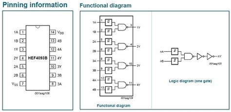
Here’s the pinout for the 14-pin DIP package:
| Pin | Function |
|---|---|
| 1 | 1A (Input) |
| 2 | 1B (Input) |
| 3 | 1Y (Output) |
| 4 | 2A (Input) |
| 5 | 2B (Input) |
| 6 | 2Y (Output) |
| 7 | GND |
| 8 | 3Y (Output) |
| 9 | 3B (Input) |
| 10 | 3A (Input) |
| 11 | 4Y (Output) |
| 12 | 4B (Input) |
| 13 | 4A (Input) |
| 14 | VCC |
Schmitt Trigger Inputs
One of the key features of the IC 4093 is its Schmitt trigger inputs. A Schmitt trigger is a comparator circuit with hysteresis, which means that it has different threshold voltages for rising and falling input signals. This hysteresis helps to improve the noise immunity of the circuit by preventing unintended switching due to small fluctuations in the input signal.
The Schmitt trigger inputs of the IC 4093 have the following characteristics:
- Positive-going threshold voltage (VT+): 0.6 × VCC
- Negative-going threshold voltage (VT-): 0.4 × VCC
These threshold voltages ensure that the output of the NAND gate only changes state when the input signal crosses the appropriate threshold, reducing the likelihood of false triggering due to noise.

NAND Gate Truth Table
The IC 4093 contains four 2-input NAND gates. A NAND gate is a universal logic gate that produces a LOW output only when all its inputs are HIGH. The truth table for a 2-input NAND gate is as follows:
| Input A | Input B | Output Y |
|---|---|---|
| 0 | 0 | 1 |
| 0 | 1 | 1 |
| 1 | 0 | 1 |
| 1 | 1 | 0 |
Applications of the IC 4093
The IC 4093’s combination of NAND gates and Schmitt trigger inputs makes it suitable for a wide range of digital logic applications, such as:
- Pulse shaping and conditioning
- Debouncing switches
- Implementing simple logic functions
- Building oscillators and astable multivibrators
- Creating monostable multivibrators (one-shot pulses)
- Interfacing with sensors and other devices
Pulse Shaping and Conditioning
In digital systems, it’s often necessary to condition input signals to ensure they have clean, sharp edges and are free from noise. The IC 4093’s Schmitt trigger inputs make it an excellent choice for pulse shaping and conditioning applications.
For example, you can use a single NAND gate of the IC 4093 as an inverting Schmitt trigger by connecting one input to the signal source and the other input to the output, like this:
        ┌───────────┐
Input ──┤1A      1Y ├── Output
        │           │
        │1B         │
        └───────────┘
This configuration will produce a clean, inverted output signal with sharp edges, even if the input signal is noisy or has slow rise and fall times.
Debouncing Switches
Mechanical switches, such as pushbuttons and toggle switches, often produce unwanted contact bounce when they are opened or closed. This bounce can cause multiple false transitions in the digital signal, leading to erratic behavior in the circuit. Debouncing is the process of filtering out these false transitions to produce a clean, stable signal.
The IC 4093 can be used to debounce switches by taking advantage of its Schmitt trigger inputs and the hysteresis they provide. A simple debounce circuit using a single NAND gate of the IC 4093 looks like this:
                  ┌───────────┐
                  │           │
                  │1A      1Y │
                  │           │
                  │1B         │
         ┌───┐    └───────────┘
Switch ──┤ _ │    │
         └┬─┬┘    │
          │ │     │
          └─┴─────┘
           │
           └─ GND
The resistor and capacitor form an RC filter that slows down the transitions of the switch signal, while the Schmitt trigger input provides hysteresis to prevent false triggering. The result is a clean, debounced output signal.
Implementing Simple Logic Functions
Since the IC 4093 contains four 2-input NAND gates, it can be used to implement various simple logic functions. NAND gates are universal gates, meaning that any other logic function can be built using only NAND gates.
For example, you can create an AND gate by inverting the output of a NAND gate:
        ┌───────────┐
Input A ┤1A      1Y ├──┐
        │           │  │ ┌───────────┐
Input B ┤1B         │  └─┤2A      2Y ├── Output (A AND B)
        └───────────┘    │           │
                         └───────────┘
Similarly, you can create an OR gate by first inverting the inputs using NAND gates, then combining the inverted signals with another NAND gate:
        ┌───────────┐
Input A ┤1A      1Y ├──┐
        │           │  │ ┌───────────┐
        └───────────┘  └─┤3A         │
                         │        3Y ├── Output (A OR B)
        ┌───────────┐  ┌─┤3B         │
Input B ┤2A      2Y ├──┘ └───────────┘
        │           │
        └───────────┘
Building Oscillators and Astable Multivibrators
An astable multivibrator, also known as a free-running oscillator, is a circuit that produces a continuous square wave output without any external trigger. The IC 4093 can be used to build astable multivibrators by taking advantage of the Schmitt trigger inputs and the Propagation Delay of the NAND gates.
Here’s a simple astable multivibrator circuit using two NAND gates of the IC 4093:
            ┌───────────┐
            │1A      1Y │
            │           │
            │1B         │         ┌───────────┐
            └─────┬─────┘         │2A      2Y │
                  │               │           │
                 ┌┴┐              │2B         │
                 │ │ R1           └───────────┘
                 └┬┘                    │
                  │                     │
                  ├─────────────────────┘
                  │
                 ┌┴┐
                 │ │ C1
                 └┬┘
                  │
                  └─ GND
In this circuit, R1 and C1 determine the frequency of oscillation. The output of the first NAND gate (1Y) charges C1 through R1, while the output of the second NAND gate (2Y) discharges C1. The Schmitt trigger inputs provide the necessary hysteresis to sustain the oscillation.
The frequency of oscillation can be approximated using the following formula:
f ≈ 1 / (1.2 × R1 × C1)
where:
– f is the frequency in Hz
– R1 is the resistance in ohms
– C1 is the capacitance in farads
Creating Monostable Multivibrators (One-Shot Pulses)
A monostable multivibrator, also known as a one-shot Pulse Generator, is a circuit that produces a single output pulse of a predetermined duration in response to an input trigger signal. The IC 4093 can be used to create monostable multivibrators by using one NAND gate as the trigger input and another NAND gate as the pulse generator.
Here’s a simple monostable multivibrator circuit using two NAND gates of the IC 4093:
                ┌───────────┐
Trigger Input ──┤1A      1Y │
                │           │         ┌───────────┐
                │1B         │         │2A      2Y ├── Output Pulse
                └───────────┘         │           │
                                      │2B         │
                                      └─────┬─────┘
                                            │
                                           ┌┴┐
                                           │ │ R1
                                           └┬┘
                                            │
                                           ┌┴┐
                                           │ │ C1
                                           └┬┘
                                            │
                                            └─ GND
In this circuit, the first NAND gate (1A, 1B, 1Y) acts as the trigger input. When the trigger input goes LOW, it causes the output of the second NAND gate (2Y) to go HIGH. The output remains HIGH for a duration determined by the time constant of R1 and C1, after which it returns to LOW.
The pulse duration can be approximated using the following formula:
t ≈ 1.1 × R1 × C1
where:
– t is the pulse duration in seconds
– R1 is the resistance in ohms
– C1 is the capacitance in farads
Interfacing with Sensors and Other Devices
The IC 4093’s Schmitt trigger inputs and wide supply voltage range make it a useful component for interfacing with various sensors and other devices. For example, you can use the IC 4093 to condition the output signal of a sensor before feeding it to a microcontroller or other digital system.
Here’s an example of using the IC 4093 to interface with a PIR (Passive Infrared) motion sensor:
                   ┌───────────┐
PIR Sensor Output ─┤1A      1Y ├── Conditioned Output
                   │           │
                   │1B         │
                   └───────────┘
In this simple configuration, the Schmitt trigger input of the NAND gate helps to clean up the potentially noisy output signal from the PIR sensor, providing a more reliable signal for further processing.
Frequently Asked Questions (FAQ)
-
What is the difference between the IC 4093 and the IC 4011?
The IC 4093 and the IC 4011 are both quad 2-input NAND gate ICs, but the main difference is that the IC 4093 has Schmitt trigger inputs, while the IC 4011 does not. This means that the IC 4093 has better noise immunity and is more suitable for applications where the input signals may be slow or noisy. -
Can the IC 4093 be used with a 5V supply voltage?
Yes, the IC 4093 is designed to work with a wide range of supply voltages, from 3V to 15V. It is fully compatible with 5V logic systems. -
How can I calculate the values of R1 and C1 for an astable multivibrator circuit?
To calculate the values of R1 and C1 for a desired frequency, you can use the formula:
f ≈ 1 / (1.2 × R1 × C1)
First, choose a suitable capacitor value (C1) based on the desired frequency range and the available component values. Then, rearrange the formula to solve for R1:
R1 ≈ 1 / (1.2 × f × C1)
For example, if you want an oscillation frequency of 1 kHz and have chosen a capacitor value of 10 nF, you can calculate the required resistance as follows:
R1 ≈ 1 / (1.2 × 1000 Hz × 10 × 10⁻⁹ F) ≈ 83.3 kΩ
In practice, you would choose the nearest standard resistor value, such as 82 kΩ. -
How many NAND gates are there in an IC 4093?
The IC 4093 contains four independent 2-input NAND gates with Schmitt trigger inputs. -
What is the purpose of the Schmitt trigger inputs in the IC 4093?
The Schmitt trigger inputs in the IC 4093 provide hysteresis, which means that the switching thresholds for rising and falling input signals are different. This hysteresis helps to improve the noise immunity of the circuit by preventing unintended switching due to small fluctuations in the input signal. As a result, the IC 4093 is more suitable for applications where the input signals may be slow, noisy, or prone to interference.
Conclusion
The IC 4093 is a versatile and widely-used quad 2-input NAND Schmitt trigger integrated circuit. Its combination of NAND gates and Schmitt trigger inputs makes it suitable for a wide range of digital logic applications, such as pulse shaping, switch debouncing, implementing simple logic functions, building oscillators, creating one-shot pulses, and interfacing with sensors.
By understanding the features, pinout, truth table, and application examples of the IC 4093, you can effectively incorporate this useful component into your digital logic designs, improving the reliability and performance of your circuits.
No responses yet