Introduction to Aluminum PCB
Aluminum PCB, also known as Metal Core PCB (MCPCB), is a type of printed circuit board that uses aluminum as its base material instead of the traditional FR-4 substrate. The aluminum base provides excellent thermal conductivity, making it an ideal choice for applications that generate a significant amount of heat, such as high-power LED lighting, automotive electronics, and power converters.
Advantages of Aluminum PCB
- Enhanced thermal management
- Improved electrical performance
- Increased durability and reliability
- Lightweight and compact design
- Cost-effective solution for heat dissipation
Structure and Composition of Aluminum PCB
Layers of an Aluminum PCB
An aluminum PCB typically consists of three main layers:
- Aluminum base layer
- Dielectric layer
- Copper layer
Aluminum Base Layer
The aluminum base layer serves as the foundation of the PCB and provides excellent thermal conductivity. The thickness of the aluminum base can vary depending on the application and the required level of heat dissipation. Common aluminum alloys used in MCPCBs include:
- 5052 aluminum alloy
- 6061 aluminum alloy
Dielectric Layer
The dielectric layer is an electrically insulating material that separates the aluminum base from the copper layer. It is typically made of a thermally conductive but electrically insulating material, such as:
- Epoxy resin
- Polyimide
- Ceramic-filled polymer
The dielectric layer plays a crucial role in ensuring the electrical integrity of the PCB while allowing efficient heat transfer from the copper layer to the aluminum base.
Copper Layer
The copper layer is where the electrical components and circuits are mounted. It is usually made of high-purity copper foil and can be single-sided or double-sided, depending on the complexity of the circuit design. The thickness of the copper layer can vary based on the current carrying requirements of the application.
Thermal Conductivity Comparison
| Material | Thermal Conductivity (W/mK) |
|---|---|
| Aluminum (5052 alloy) | 138 |
| Aluminum (6061 alloy) | 167 |
| FR-4 (traditional PCB substrate) | 0.3 – 0.4 |
As seen in the table above, aluminum has a significantly higher thermal conductivity compared to the traditional FR-4 substrate, making it an excellent choice for applications that require efficient heat dissipation.

Manufacturing Process of Aluminum PCB
Step 1: Substrate Preparation
The aluminum substrate is cleaned and prepared for the application of the dielectric layer. This process may involve surface treatment techniques such as anodizing or brushing to improve adhesion and electrical insulation.
Step 2: Dielectric Layer Application
The dielectric layer is applied to the aluminum substrate using techniques such as:
- Screen printing
- Lamination
- Sputtering
The choice of application method depends on the type of dielectric material used and the desired thickness of the layer.
Step 3: Copper Foil Lamination
The copper foil is laminated onto the dielectric layer using heat and pressure. The lamination process ensures a strong bond between the copper foil and the dielectric layer, creating a stable and reliable base for the subsequent steps.
Step 4: Circuit Patterning
The desired circuit pattern is transferred onto the copper layer using photolithography and etching processes. This step involves:
- Applying a photoresist layer onto the copper foil
- Exposing the photoresist to UV light through a photomask with the circuit pattern
- Developing the photoresist to remove the exposed areas
- Etching away the unwanted copper, leaving behind the desired circuit pattern
Step 5: Surface Finish Application
A surface finish, such as HASL (Hot Air Solder Leveling) or ENIG (Electroless Nickel Immersion Gold), is applied to the exposed copper to protect it from oxidation and improve solderability.
Step 6: Solder Mask Application
A solder mask layer is applied to the PCB to protect the copper traces from short circuits and provide electrical insulation. The solder mask also helps to prevent solder bridging during the component assembly process.
Step 7: Silkscreen Printing
The silkscreen layer is printed onto the PCB to add component labels, logos, and other identifying marks. This step is important for assembly and troubleshooting purposes.
Step 8: Singulation and Finishing
The individual PCBs are cut out from the panel using routing or punching techniques. The edges of the PCBs are then smoothed and cleaned to remove any burrs or debris.

Applications of Aluminum PCB
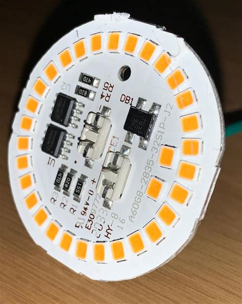
High-Power LED Lighting
Aluminum PCBs are widely used in high-power LED lighting applications due to their excellent thermal management properties. The aluminum base helps to efficiently dissipate the heat generated by the LEDs, ensuring optimal performance and longevity.
Benefits of using Aluminum PCB in LED lighting
- Improved LED lifetime and reliability
- Reduced thermal resistance
- Smaller and more compact designs
- Increased luminous efficiency
Automotive Electronics
Aluminum PCBs are increasingly used in automotive electronics, particularly in high-power applications such as:
- Engine control units (ECUs)
- Power inverters
- Battery management systems
- LED headlights and taillights
The use of aluminum PCBs in these applications helps to ensure reliable operation in the harsh environmental conditions experienced in automotive settings, such as high temperatures and vibrations.
Power Converters and Amplifiers
Aluminum PCBs are an excellent choice for power converters and amplifiers, as they can efficiently dissipate the heat generated by the high-power components. This helps to prevent thermal runaway and ensures stable operation over a wide range of operating conditions.
Examples of power converters and amplifiers using Aluminum PCB
- Switched-mode power supplies (SMPS)
- Audio power amplifiers
- Motor drives
- Uninterruptible power supplies (UPS)

Design Considerations for Aluminum PCB
Thermal Management
When designing an aluminum PCB, it is crucial to consider the thermal management aspects to ensure optimal performance and reliability. Some key factors to consider include:
- Thermal interface material (TIM) selection
- Dielectric layer thickness and thermal conductivity
- Copper layer thickness and layout
- Component placement and heat distribution
Thermal Interface Materials (TIMs)
TIMs are used to improve the thermal contact between the aluminum base and the heat-generating components. Common TIMs used in aluminum PCBs include:
- Thermal greases
- Thermal pads
- Phase change materials
The choice of TIM depends on the specific application, the required thermal performance, and the assembly process.
Electrical Insulation
Ensuring proper electrical insulation between the aluminum base and the copper layer is critical for the reliable operation of the PCB. The dielectric layer must provide sufficient insulation while allowing efficient heat transfer.
Factors affecting electrical insulation
- Dielectric layer material properties
- Dielectric layer thickness
- Voltage rating of the application
- Environmental conditions (e.g., humidity, temperature)
Component Selection and Placement
When selecting components for an aluminum PCB, it is important to consider their thermal characteristics and power dissipation requirements. Components with high power dissipation should be placed closer to the aluminum base to maximize heat transfer.
Guidelines for component placement
- Place high-power components near the center of the PCB
- Provide sufficient spacing between components to avoid thermal coupling
- Use thermal vias to improve heat transfer from the component to the aluminum base
- Consider the use of heat spreaders or heat sinks for components with very high power dissipation
Advantages and Disadvantages of Aluminum PCB
Advantages
- Excellent thermal management
- Improved electrical performance
- Increased durability and reliability
- Lightweight and compact design
- Cost-effective solution for heat dissipation
Disadvantages
- Higher manufacturing costs compared to traditional FR-4 PCBs
- Limited flexibility in design due to the rigid aluminum base
- Potential for thermal expansion mismatch between components and the aluminum base
- More complex assembly process compared to traditional PCBs
Future Trends in Aluminum PCB Technology
As the demand for high-performance electronics continues to grow, aluminum PCB technology is expected to evolve to meet the increasing thermal management and power dissipation requirements. Some key trends to watch for include:
- Development of new dielectric materials with higher thermal conductivity and electrical insulation properties
- Advancements in manufacturing processes to improve the reliability and cost-effectiveness of aluminum PCBs
- Increased adoption of aluminum PCBs in emerging applications such as electric vehicles, renewable energy systems, and 5G telecommunications infrastructure
Frequently Asked Questions (FAQ)
1. What is the difference between an aluminum PCB and a traditional FR-4 PCB?
An aluminum PCB uses an aluminum base as its substrate, providing excellent thermal conductivity, while a traditional FR-4 PCB uses a glass-reinforced epoxy laminate. Aluminum PCBs are better suited for applications that require efficient heat dissipation, while FR-4 PCBs are more commonly used in general-purpose electronics.
2. Can aluminum PCBs be used in high-voltage applications?
Yes, aluminum PCBs can be used in high-voltage applications, provided that the dielectric layer is properly designed to provide sufficient electrical insulation between the aluminum base and the copper layer. The thickness and material properties of the dielectric layer must be carefully selected based on the voltage rating of the application.
3. How does the thermal expansion mismatch between components and the aluminum base affect the reliability of aluminum PCBs?
The thermal expansion mismatch between components and the aluminum base can lead to mechanical stress and strain on the solder joints, potentially causing fatigue and failure over time. To mitigate this issue, designers can use thermal interface materials, underfill materials, or Flexible Circuit Designs to accommodate the differential thermal expansion.
4. Are aluminum PCBs more expensive than traditional FR-4 PCBs?
Yes, aluminum PCBs are generally more expensive than traditional FR-4 PCBs due to the higher cost of the aluminum substrate and the more complex manufacturing process. However, the improved thermal management and reliability offered by aluminum PCBs can offset the higher initial costs in applications that require efficient heat dissipation.
5. What are the key considerations when designing an aluminum PCB for a specific application?
When designing an aluminum PCB for a specific application, key considerations include:
- Thermal management requirements and the selection of appropriate thermal interface materials
- Electrical insulation and the choice of dielectric layer material and thickness
- Component selection and placement based on power dissipation and thermal characteristics
- Manufacturing process and the associated costs and lead times
- Reliability and durability requirements based on the operating environment and expected product lifetime
Conclusion
Aluminum PCBs offer a valuable solution for applications that require efficient thermal management and high power dissipation. By understanding the structure, composition, and manufacturing process of aluminum PCBs, designers can leverage their advantages to create high-performance electronics for a wide range of industries.
As the demand for reliable and efficient electronics continues to grow, aluminum PCB technology is poised to play an increasingly important role in enabling the next generation of high-power applications. By staying informed about the latest trends and advancements in aluminum PCB design and manufacturing, engineers and designers can create innovative products that meet the evolving needs of the market.
No responses yet