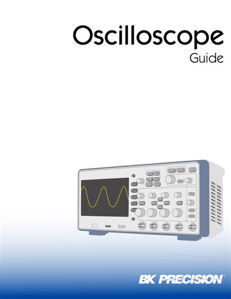
What is an Oscilloscope?
An oscilloscope is an electronic test instrument that displays and measures electrical signals. It shows how a signal changes over time, with voltage on the vertical axis and time on the horizontal axis. This allows you to see the shape, frequency, and amplitude of the signal, as well as any distortion or noise.
Oscilloscopes come in a variety of types and sizes, from small handheld units to large benchtop models. They can have analog or digital displays, and may include features such as built-in signal generators, spectrum analyzers, and protocol analyzers.
How Does an Oscilloscope Work?
At its core, an oscilloscope consists of a cathode ray tube (CRT) or liquid crystal display (LCD) screen, a vertical amplifier, a horizontal amplifier, and a trigger circuit.
The vertical amplifier amplifies the input signal and applies it to the vertical deflection plates of the CRT or LCD. The horizontal amplifier generates a sawtooth waveform that sweeps the electron beam or LCD pixels horizontally across the screen at a constant rate.
The trigger circuit synchronizes the horizontal sweep with the input signal, ensuring that the waveform starts at the same point on the screen each time it is displayed. This allows you to see a stable, repeatable waveform even if the signal is not periodic.

Basic Oscilloscope Controls
Before you start using an oscilloscope, it’s important to familiarize yourself with the basic controls. While the exact layout may vary between models, most oscilloscopes have the following controls:
- Power switch: Turns the oscilloscope on and off.
- Vertical scale: Adjusts the sensitivity of the vertical amplifier, measured in volts per division (V/div).
- Horizontal scale: Adjusts the sweep speed of the horizontal amplifier, measured in seconds per division (s/div).
- Trigger level: Sets the voltage level at which the trigger circuit will start the horizontal sweep.
- Trigger slope: Selects whether the trigger will occur on the rising or falling edge of the signal.
- Trigger source: Selects the source of the trigger signal, which can be the input signal, an external source, or the AC line voltage.
- Input coupling: Selects whether the input signal is AC-coupled (blocking any DC component) or DC-coupled (allowing both AC and DC components).
- Input attenuation: Adjusts the input signal level to prevent overloading the vertical amplifier.

Setting Up an Oscilloscope
To set up an oscilloscope, follow these steps:
- Connect the oscilloscope probe to the input channel you want to use. Make sure the probe is properly compensated and calibrated.
- Connect the probe ground lead to the circuit ground or a known reference point.
- Set the vertical and horizontal scales to appropriate values for the signal you want to measure. You may need to adjust these settings later to get a clear view of the waveform.
- Set the trigger level and slope to capture the desired portion of the waveform. You may need to experiment with different trigger settings to get a stable display.
- Adjust the input coupling and attenuation as needed to prevent overloading the vertical amplifier or distorting the waveform.

Measuring Signals with an Oscilloscope
Once you have your oscilloscope set up, you can start measuring signals. Here are some common measurements you can make:
Voltage Measurements
To measure the voltage of a signal, use the vertical scale to determine the peak-to-peak voltage (Vpp) or the RMS voltage (Vrms). The peak-to-peak voltage is the difference between the maximum and minimum values of the waveform, while the RMS voltage is the effective value of an AC signal.
| Waveform | Peak-to-Peak Voltage | RMS Voltage |
|---|---|---|
| Sine wave | 2 × Vmax | 0.707 × Vmax |
| Square wave | Vmax – Vmin | Vmax |
| Triangle wave | Vmax – Vmin | 0.577 × Vmax |
Time Measurements
To measure the time interval between two points on a waveform, use the horizontal scale to determine the time per division. You can then count the number of divisions between the two points and multiply by the time per division to get the time interval.
For example, if the horizontal scale is set to 1 ms/div and there are 5 divisions between two points, the time interval is:
5 div × 1 ms/div = 5 ms
Frequency Measurements
To measure the frequency of a periodic signal, you can use the time measurement technique to determine the period (T) of the waveform. The frequency (f) is then the reciprocal of the period:
f = 1 / T
For example, if the period of a waveform is 2 ms, the frequency is:
f = 1 / 2 ms = 500 Hz
Advanced Oscilloscope Techniques
Once you’re comfortable with the basics of using an oscilloscope, you can start exploring some more advanced techniques:
Triggering
Triggering is the process of synchronizing the horizontal sweep with the input signal. By adjusting the trigger level and slope, you can capture specific events or portions of the waveform. Some advanced triggering modes include:
- Edge triggering: Triggers on the rising or falling edge of the signal.
- Pulse width triggering: Triggers on pulses that are wider or narrower than a specified time.
- Slope triggering: Triggers on signals that are rising or falling at a specified rate.
- Video triggering: Triggers on specific lines or fields of a video signal.
Cursors
Cursors are movable markers that allow you to make precise measurements on a waveform. There are two main types of cursors:
- Voltage cursors: Measure the voltage difference between two points on the waveform.
- Time cursors: Measure the time difference between two points on the waveform.
Math Functions
Many oscilloscopes include built-in math functions that allow you to perform calculations on the input signals. Some common math functions include:
- Addition: Adds two input signals together.
- Subtraction: Subtracts one input signal from another.
- Multiplication: Multiplies two input signals together.
- FFT: Computes the Fast Fourier Transform of an input signal to display its frequency spectrum.
FAQs
- What is the difference between an analog and digital oscilloscope?
-
An analog oscilloscope uses a CRT to display the waveform, while a digital oscilloscope uses an LCD or other digital display. Digital oscilloscopes can store and analyze waveforms, while analog oscilloscopes can only display them in real-time.
-
How do I choose the right oscilloscope for my needs?
-
When choosing an oscilloscope, consider factors such as bandwidth, sample rate, memory depth, number of channels, and available features. Make sure the oscilloscope has enough bandwidth and sample rate to accurately capture the signals you need to measure.
-
What is the purpose of oscilloscope probes?
-
Oscilloscope probes are used to connect the oscilloscope to the circuit being tested. They provide electrical isolation and signal conditioning to ensure accurate measurements. Different types of probes are available for different applications, such as high voltage or high frequency measurements.
-
Can an oscilloscope measure current?
-
An oscilloscope typically measures voltage, but it can be used to indirectly measure current by using a current probe or by measuring the voltage drop across a known resistance.
-
How do I calibrate my oscilloscope?
- Most modern oscilloscopes include built-in calibration routines that can be run periodically to ensure accurate measurements. Consult your oscilloscope’s manual for specific calibration instructions.
In conclusion, an oscilloscope is a powerful tool for analyzing and measuring electrical signals. By understanding the basic controls, setup procedures, and measurement techniques, you can use an oscilloscope to troubleshoot circuits, design new systems, and explore the world of electronics. With practice and experience, you can master advanced techniques and unlock the full potential of your oscilloscope.
No responses yet