What is a Diode and How Does it Work?
A diode is a two-terminal electronic component that conducts current primarily in one direction (asymmetric conductance). It has low resistance in one direction, and high resistance in the other. The most common function of a diode is to allow an electric current to pass in one direction (called the diode’s forward direction), while blocking it in the opposite direction (the reverse direction).
The basic structure of a diode consists of two semiconductor materials, usually silicon, that are doped with impurities to create a p-n junction. The p-side contains an excess of holes, while the n-side contains an excess of electrons. When a voltage is applied across the diode, it allows current to flow easily from the p-side to the n-side, but not in the reverse direction.
Types of Diodes
There are several types of diodes, each designed for specific applications:
- Rectifier Diodes: Used to convert alternating current (AC) to direct current (DC).
- Zener Diodes: Used for voltage regulation and Overvoltage Protection.
- Light-Emitting Diodes (LEDs): Used for illumination and indicator lights.
- Schottky Diodes: Used in high-frequency applications and for voltage clamping.
- Avalanche Diodes: Used for voltage protection and in avalanche breakdown regions.
Why is Diode Testing Important?
Diode testing is crucial to ensure the proper functioning of electronic circuits. Faulty diodes can lead to various problems, such as:
- Incorrect current flow: A faulty diode may allow current to flow in the wrong direction or not at all, causing the circuit to malfunction.
- Overheating: If a diode fails short-circuit, it can draw excessive current, leading to overheating and potential damage to other components.
- Signal distortion: In signal processing applications, a faulty diode can introduce distortion or clipping, affecting the quality of the output signal.
- Power supply issues: In power supply circuits, a failing diode can cause voltage regulation problems or complete power failure.
Regular diode testing helps identify faulty components before they cause more extensive damage to the circuit. It also aids in troubleshooting and repairing electronic devices.

Diode Testing Methods
There are several methods to test diodes, each with its advantages and limitations. The most common diode testing methods include:
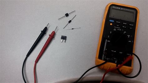
1. Multimeter Testing
A multimeter is a versatile tool that can be used to test diodes. Most digital multimeters have a dedicated diode test function, which applies a small voltage across the diode and measures the voltage drop.
To test a diode using a multimeter:
- Set the multimeter to the diode test function (usually indicated by a diode symbol).
- Connect the red (positive) lead to the anode and the black (negative) lead to the cathode of the diode.
- If the diode is functioning correctly, the multimeter will display a voltage drop between 0.5V and 0.8V for a silicon diode, or 0.2V to 0.4V for a germanium diode.
- Reverse the leads and repeat the test. A good diode should display an open circuit (OL) in the reverse direction.
If the multimeter displays a voltage drop in both directions or an open circuit in both directions, the diode is likely faulty.
2. Oscilloscope Testing
An oscilloscope is a valuable tool for testing diodes in dynamic circuits. It allows you to observe the voltage waveform across the diode and detect any abnormalities.
To test a diode using an oscilloscope:
- Set up the oscilloscope to display the appropriate voltage range and time base for your circuit.
- Connect the oscilloscope probes across the diode, with the ground lead connected to the cathode and the signal lead connected to the anode.
- Apply power to the circuit and observe the waveform on the oscilloscope.
- A functioning diode should display a voltage drop when conducting and a flat line when not conducting.
If the oscilloscope shows a voltage drop in both directions or no voltage drop at all, the diode may be faulty.
3. Curve Tracer Testing
A curve tracer is a specialized instrument designed for testing semiconductor devices, including diodes. It provides a visual representation of the diode’s current-voltage (I-V) characteristics, making it easier to identify faulty components.
To test a diode using a curve tracer:
- Set up the curve tracer according to the manufacturer’s instructions, selecting the appropriate voltage and current ranges for your diode.
- Connect the diode to the curve tracer, ensuring the anode and cathode are correctly connected.
- Adjust the voltage and current settings to obtain a clear I-V curve on the display.
- Compare the displayed curve with the expected I-V characteristics for the specific diode type.
A faulty diode may display an abnormal I-V curve, such as excessive leakage current, a short circuit, or an open circuit.
Comparison of Diode Testing Methods
| Method | Advantages | Disadvantages |
|---|---|---|
| Multimeter Testing | – Simple and quick – Widely available – Suitable for most diode types |
– Limited to static testing – May not detect subtle faults |
| Oscilloscope Testing | – Allows dynamic testing – Can detect intermittent faults – Provides visual waveform analysis |
– Requires setup and interpretation skills – Limited to in-circuit testing |
| Curve Tracer Testing | – Comprehensive I-V characteristic analysis – Suitable for all diode types – Easy fault identification |
– Expensive equipment – Requires device removal from the circuit |

Interpreting Diode Test Results
When interpreting diode test results, it’s essential to consider the specific diode type and its expected characteristics. However, some general guidelines can help identify faulty diodes:
- Short circuit: A diode that conducts in both directions with a low voltage drop is likely short-circuited.
- Open circuit: A diode that does not conduct in either direction is likely open-circuited.
- High forward voltage drop: A diode with a forward voltage drop significantly higher than expected may be faulty or damaged.
- Excessive leakage current: A diode that conducts a significant amount of current in the reverse direction may have excessive leakage.
It’s important to note that some diodes, such as Zener diodes and LEDs, have unique characteristics and may require specific testing methods and interpretation.

Frequently Asked Questions (FAQ)
-
Q: Can a multimeter damage a diode during testing?
A: Most modern multimeters have a dedicated diode test function that applies a small, safe voltage across the diode. This voltage is typically not high enough to damage the diode. However, using the wrong multimeter setting, such as the resistance or continuity function, can potentially damage the diode. -
Q: How do I know the polarity of an unmarked diode?
A: If a diode is unmarked, you can determine its polarity using a multimeter’s diode test function. Connect the red (positive) lead to one end of the diode and the black (negative) lead to the other end. If the multimeter displays a voltage drop, the end connected to the red lead is the anode, and the end connected to the black lead is the cathode. If the multimeter displays an open circuit, reverse the leads and try again. -
Q: Can I test a diode while it’s still in the circuit?
A: In some cases, you can test a diode while it’s still in the circuit using a multimeter or oscilloscope. However, the circuit’s other components may influence the test results, making it difficult to accurately assess the diode’s condition. For the most reliable results, it’s best to remove the diode from the circuit and test it individually. -
Q: What is the difference between a silicon and germanium diode?
A: Silicon and germanium are two semiconductor materials used to manufacture diodes. Silicon diodes have a higher forward voltage drop (0.6V to 0.7V) compared to germanium diodes (0.2V to 0.3V). Silicon diodes are more common in modern electronics due to their better temperature stability and higher reverse breakdown voltage. Germanium diodes are less common but are still used in some low-voltage, high-frequency applications. -
Q: How often should I test the diodes in my electronic devices?
A: The frequency of diode testing depends on the specific application and the device’s operating conditions. For critical applications or devices exposed to harsh environments, more frequent testing may be necessary. As a general rule, it’s a good idea to test diodes during routine maintenance, troubleshooting, or when you suspect a problem with the device’s performance. If a diode fails, it’s important to replace it promptly to prevent further damage to the circuit.
Conclusion
Diode testing is an essential skill for anyone working with electronic circuits. By understanding the different testing methods and interpreting the results correctly, you can quickly identify faulty diodes and prevent potential problems. Whether using a multimeter, oscilloscope, or curve tracer, regular diode testing will help ensure the proper functioning and longevity of your electronic devices.
No responses yet