Understanding QFP and Solder Bridging
What is QFP?
QFP, or Quad Flat Package, is a surface-mount integrated circuit package with leads extending from all four sides. It is a popular choice for many electronic components due to its compact size and high lead count. QFPs come in various sizes, with the most common being:
| QFP Type | Lead Count | Pitch (mm) |
|---|---|---|
| TQFP | 32-176 | 0.4-0.8 |
| LQFP | 32-256 | 0.3-0.65 |
| PQFP | 44-304 | 0.4-1.0 |
| VQFP | 32-256 | 0.4-0.8 |
What is Solder Bridging?
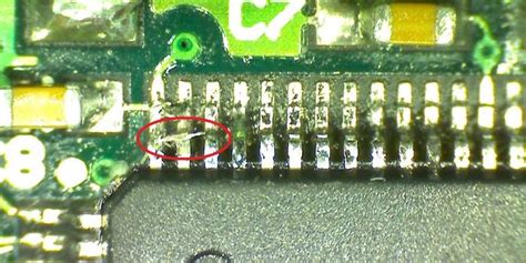
Solder bridging is a common problem that occurs when soldering QFPs. It happens when excess solder creates an unintended connection between two or more leads, causing short circuits and potentially damaging the component or the entire circuit board. Solder bridging can be caused by various factors, such as:
- Excessive solder paste application
- Improper solder paste viscosity
- Incorrect reflow profile
- Poor stencil design or alignment
- Inadequate cleaning of the PCB before soldering
Preventing Solder Bridging
Proper Solder Paste Application
One of the most effective ways to prevent solder bridging is to ensure the correct amount of solder paste is applied to the PCB. This can be achieved by using a well-designed stencil and a solder paste printer with precise controls. The stencil aperture size and shape should be optimized for the specific QFP package, and the solder paste should be applied evenly across the pads.
Solder Paste Viscosity
The viscosity of the solder paste plays a crucial role in preventing solder bridging. If the paste is too thick, it may not flow properly during reflow, resulting in excessive solder on the pads. On the other hand, if the paste is too thin, it may slump and cause bridging between the leads. The ideal viscosity range for solder paste is between 800,000 and 1,200,000 centipoise (cP).
Reflow Profile Optimization
The reflow profile should be carefully optimized to ensure proper solder joint formation and minimize the risk of bridging. The key parameters to consider are:
- Preheat temperature and duration
- Soak time and temperature
- Reflow peak temperature and duration
- Cooling rate
A well-designed reflow profile will allow the solder paste to melt and flow evenly, creating strong and reliable solder joints without bridging.
Stencil Design and Alignment
The stencil design and alignment are critical factors in preventing solder bridging. The stencil apertures should be sized and shaped to match the PCB pads, with appropriate clearances to avoid paste overflow. The stencil should also be aligned precisely with the PCB to ensure the paste is deposited in the correct locations.
PCB Cleaning
Proper cleaning of the PCB before soldering can help prevent solder bridging by removing any contaminants or residues that may interfere with the soldering process. This can be done using various methods, such as:
- Isopropyl alcohol (IPA) cleaning
- Plasma cleaning
- Ultrasonic cleaning

Detecting and Correcting Solder Bridging
Visual Inspection
Visual inspection is the most common method for detecting solder bridging. This can be done using a microscope or a high-resolution camera to examine the solder joints closely. Bridging can be identified by the presence of excess solder connecting two or more leads.
Automated Optical Inspection (AOI)
AOI systems use high-resolution cameras and advanced image processing algorithms to detect solder bridging and other soldering defects automatically. These systems can quickly scan the entire PCB and highlight any areas of concern, allowing for rapid identification and correction of bridging issues.
X-Ray Inspection
For complex or densely populated PCBs, X-ray inspection may be necessary to detect solder bridging that is not visible from the surface. X-ray systems can penetrate the PCB and create detailed images of the solder joints, revealing any hidden bridging or other defects.
Correcting Solder Bridging
Once solder bridging has been detected, it must be corrected to ensure the proper functioning of the circuit. The most common methods for correcting bridging are:
- Solder wick: A copper braid that is used to absorb excess solder from the bridged leads.
- Solder sucker: A vacuum tool that is used to remove excess solder from the bridged leads.
- Rework station: A specialized tool that uses a fine-tipped soldering iron and a microscope to carefully remove the excess solder and reshape the solder joints.

Best Practices for QFP Soldering
To minimize the risk of solder bridging and ensure high-quality solder joints, follow these best practices:
- Use a well-designed stencil with appropriate aperture sizes and shapes.
- Ensure proper solder paste viscosity and storage conditions.
- Optimize the reflow profile for the specific QFP package and PCB design.
- Maintain precise stencil alignment and PCB Cleanliness.
- Implement a robust inspection process, including visual, AOI, and X-ray methods.
- Provide adequate training for soldering technicians and operators.
- Regularly maintain and calibrate soldering equipment and tools.

Frequently Asked Questions (FAQ)
1. What is the most common cause of solder bridging in QFPs?
The most common cause of solder bridging in QFPs is excessive solder paste application, which can result from improper stencil design, incorrect paste viscosity, or poor printing process control.
2. How can I tell if my reflow profile is causing solder bridging?
If you observe solder bridging consistently across multiple PCBs, it may indicate an issue with your reflow profile. Review the profile parameters, such as peak temperature, soak time, and cooling rate, and make adjustments as needed to optimize solder joint formation.
3. Can solder bridging be prevented entirely?
While it is not possible to prevent solder bridging entirely, the risk can be significantly reduced by implementing proper process controls, using well-designed stencils and reflow profiles, and maintaining a clean and well-aligned soldering environment.
4. What is the best way to remove solder bridges?
The best way to remove solder bridges depends on the size and location of the bridge. For small bridges, a solder wick or solder sucker can be used to absorb the excess solder. For larger or more complex bridges, a rework station with a fine-tipped soldering iron may be necessary.
5. How can I improve my QFP soldering process?
To improve your QFP soldering process, focus on the following areas:
- Stencil design and alignment
- Solder paste selection and application
- Reflow profile optimization
- PCB cleanliness and handling
- Inspection and rework processes
- Training and skill development for soldering technicians
By continuously monitoring and refining these aspects of your soldering process, you can achieve consistently high-quality QFP solder joints with minimal bridging and other defects.

No responses yet