Introduction to LED Flasher Circuits
An LED flasher circuit is a simple electronic circuit that makes an LED (Light Emitting Diode) flash on and off repeatedly. These circuits are widely used in various applications such as indicators, warning lights, decorative lighting, and even in some electronic projects for beginners to learn about basic electronics.
LED flasher circuits can be built using different methods and components, depending on the desired flashing rate, brightness, and complexity. In this article, we will explore various types of LED flasher circuits, their working principles, and step-by-step guides on how to build them.
Table of Contents
- What is an LED?
- Basic Components Required for LED Flasher Circuits
- Simple LED Flasher Circuit Using a Transistor
- LED Flasher Circuit Using a 555 Timer IC
- Adjustable LED Flasher Circuit
- Multi-LED Flasher Circuits
- Troubleshooting LED Flasher Circuits
- Applications of LED Flasher Circuits
- FAQ
- Conclusion
What is an LED?
An LED, or Light Emitting Diode, is a semiconductor device that emits light when an electric current passes through it. LEDs are widely used in various applications due to their energy efficiency, long lifespan, and small size compared to traditional incandescent bulbs.
LEDs have two terminals, called the anode (positive) and cathode (negative). When a suitable voltage is applied across these terminals, with the anode being more positive than the cathode, the LED will illuminate. The required voltage depends on the color and type of the LED, but typically ranges from 1.5V to 3.3V.

Basic Components Required for LED Flasher Circuits
To build an LED flasher circuit, you will need the following basic components:
- LEDs
- Resistors
- Capacitors
- Transistors (BJT or MOSFET)
- Integrated Circuits (ICs) such as the 555 timer
- Breadboard or PCB (Printed Circuit Board)
- Connecting wires
- Power source (battery or DC power supply)
The specific components and their values will depend on the type of LED flasher circuit you are building.

Simple LED Flasher Circuit Using a Transistor
One of the simplest LED flasher circuits can be built using a transistor, resistors, and capacitors. This circuit works on the principle of a relaxation oscillator, where the transistor alternately charges and discharges the capacitor, causing the LED to flash.
Components Required
- 1 × LED
- 1 × NPN transistor (e.g., 2N2222, BC547)
- 2 × Resistors (1kΩ and 100kΩ)
- 1 × Capacitor (100μF, electrolytic)
- 1 × Battery (9V) or DC power supply
- Connecting wires
- Breadboard or PCB
Circuit diagram
[Insert circuit diagram image here]
Step-by-Step Guide
- Connect the positive terminal of the battery to the collector of the transistor.
- Connect the 1kΩ resistor between the base of the transistor and the positive terminal of the LED.
- Connect the negative terminal of the LED to the emitter of the transistor.
- Connect the 100kΩ resistor between the base and emitter of the transistor.
- Connect the positive lead of the capacitor to the base of the transistor and the negative lead to the ground (negative terminal of the battery).
- Double-check all connections and power on the circuit.
The LED should now flash at a rate determined by the values of the resistors and capacitor. You can experiment with different values to change the flashing rate.

LED Flasher Circuit Using a 555 Timer IC
The 555 timer is a versatile integrated circuit that can be used to create various timing and oscillator circuits, including LED flashers. This method provides more control over the flashing rate and duty cycle compared to the simple transistor-based circuit.
Components Required
- 1 × LED
- 1 × 555 timer IC
- 2 × Resistors (1kΩ and 10kΩ)
- 2 × Capacitors (0.1μF, ceramic and 10μF, electrolytic)
- 1 × Battery (9V) or DC power supply
- Connecting wires
- Breadboard or PCB
Circuit Diagram
[Insert circuit diagram image here]
Step-by-Step Guide
- Connect pin 8 of the 555 timer to the positive terminal of the battery and pin 1 to the ground (negative terminal of the battery).
- Connect the 1kΩ resistor between pin 3 of the 555 timer and the positive terminal of the LED.
- Connect the negative terminal of the LED to the ground.
- Connect the 10kΩ resistor between pins 7 and 8 of the 555 timer.
- Connect the 0.1μF capacitor between pin 5 of the 555 timer and the ground.
- Connect the positive lead of the 10μF capacitor to pins 2 and 6 of the 555 timer, and the negative lead to the ground.
- Double-check all connections and power on the circuit.
The LED should now flash at a rate determined by the values of the resistor connected between pins 7 and 8, and the capacitor connected to pins 2 and 6. You can adjust these values to change the flashing rate.
Adjustable LED Flasher Circuit
An adjustable LED flasher circuit allows you to change the flashing rate using a potentiometer. This circuit is based on the 555 timer IC, with the addition of a potentiometer to control the timing resistor.
Components Required
- 1 × LED
- 1 × 555 timer IC
- 1 × Resistor (1kΩ)
- 1 × Potentiometer (100kΩ)
- 2 × Capacitors (0.1μF, ceramic and 10μF, electrolytic)
- 1 × Battery (9V) or DC power supply
- Connecting wires
- Breadboard or PCB
Circuit Diagram
[Insert circuit diagram image here]
Step-by-Step Guide
- Follow steps 1-3 and 5-6 from the “LED Flasher Circuit Using a 555 Timer IC” section.
- Connect one end of the 100kΩ potentiometer to pin 7 of the 555 timer, the other end to pin 8, and the wiper (middle pin) to pins 2 and 6.
- Double-check all connections and power on the circuit.
Adjust the potentiometer to change the flashing rate of the LED.
Multi-LED Flasher Circuits
Multi-LED flasher circuits allow you to control multiple LEDs, creating various patterns and sequences. These circuits can be built using transistors, 555 timer ICs, or microcontrollers like the Arduino.
Example: Alternating Two-LED Flasher Using a 555 Timer IC
Components Required
- 2 × LEDs (different colors)
- 1 × 555 timer IC
- 2 × Resistors (1kΩ)
- 1 × Potentiometer (100kΩ)
- 2 × Capacitors (0.1μF, ceramic and 10μF, electrolytic)
- 1 × Battery (9V) or DC power supply
- Connecting wires
- Breadboard or PCB
Circuit Diagram
[Insert circuit diagram image here]
Step-by-Step Guide
- Follow steps 1-2 and 5-6 from the “Adjustable LED Flasher Circuit” section.
- Connect the 1kΩ resistors between pin 3 of the 555 timer and the positive terminals of the LEDs.
- Connect the negative terminals of the LEDs to pins 1 and 6 of the 555 timer, respectively.
- Double-check all connections and power on the circuit.
The two LEDs should now flash alternately, with the flashing rate adjustable using the potentiometer.
Troubleshooting LED Flasher Circuits
If your LED flasher circuit is not working as expected, follow these troubleshooting steps:
- Check the polarity of the LED: Ensure that the LED is connected with the correct polarity (anode to the positive voltage and cathode to the ground or negative voltage).
- Verify the power supply: Make sure that the battery or DC power supply is providing the correct voltage and is properly connected to the circuit.
- Check the component values: Ensure that the resistors, capacitors, and other components have the correct values as specified in the circuit diagram.
- Inspect the connections: Double-check all connections, making sure that the components are properly inserted into the breadboard or PCB and that there are no loose or shorted connections.
- Test the components individually: If possible, test each component separately to identify any faulty ones. Replace any damaged or malfunctioning components.
If the circuit still does not work after following these steps, recheck the circuit diagram and connections, and consult the datasheet of the components used for any specific requirements or limitations.
Applications of LED Flasher Circuits
LED flasher circuits have numerous applications in various fields, such as:
-
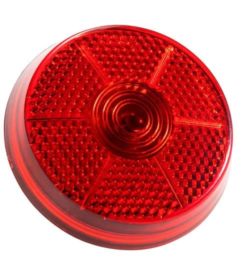
Indicators: LED flashers are commonly used as visual indicators in electronic devices, alerting users to specific conditions or states (e.g., power on, battery low, or data transmission).
-
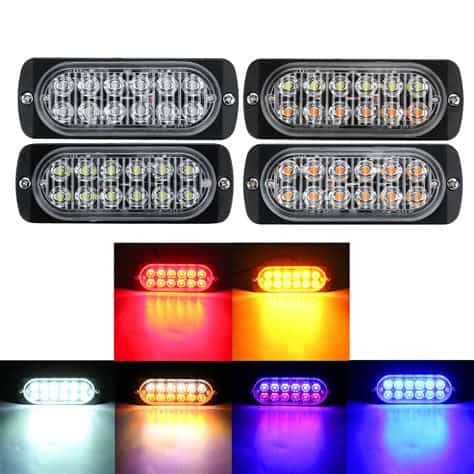
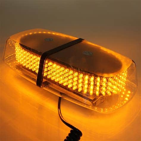
Warning lights: Flashing LED lights are used in emergency vehicles, road signs, and safety equipment to draw attention and alert people to potential hazards.
-
Decorative lighting: LED flasher circuits are used in decorative lighting applications, such as holiday lights, party decorations, and electronic jewelry.
-
Toys and games: Flashing LEDs are often incorporated into toys and electronic games to create visual effects and enhance user engagement.
-
Education: Simple LED flasher circuits are often used in educational settings to teach students about basic electronics, Circuit design, and programming concepts.
FAQ
-
Q: Can I use any type of LED for these flasher circuits?
A: Most low-power LEDs can be used in these circuits. However, ensure that the Current-Limiting Resistor is appropriately sized for the specific LED you are using to prevent damage. -
Q: How do I change the flashing rate of the LED?
A: The flashing rate can be adjusted by changing the values of the timing resistors and capacitors in the circuit. Increasing the resistance or capacitance will slow down the flashing rate, while decreasing these values will speed it up. -
Q: Can I power these circuits using a USB port instead of a battery?
A: Yes, you can power these circuits using a USB port, as long as you ensure that the voltage and current requirements are met. Most USB ports provide a 5V supply, which is suitable for these circuits. -
Q: Can I control the brightness of the LED in these flasher circuits?
A: The brightness of the LED can be controlled by adjusting the current-limiting resistor. A lower resistance will result in a brighter LED, while a higher resistance will make the LED dimmer. However, be cautious not to exceed the maximum current rating of the LED. -
Q: Are there any safety precautions I should take when building LED flasher circuits?
A: Always ensure that the components are rated for the voltage and current you are using. Avoid touching exposed wires or connections when the circuit is powered on, and never exceed the maximum ratings of the components. If you are unsure about any aspect of the circuit, consult an experienced electronics technician or engineer.
Conclusion
LED flasher circuits are simple yet versatile projects that can be built using a variety of components and methods. By understanding the basic principles behind these circuits, you can create your own custom LED flashers for various applications, from simple indicators to complex light displays.
Remember to always follow proper safety guidelines and double-check your connections before powering on the circuit. With practice and experimentation, you can develop your skills in electronic circuit design and create increasingly sophisticated LED flasher projects.

No responses yet