What are SMD Components?
Surface Mount Devices (SMDs) are electronic components that are designed to be mounted directly onto the surface of a printed circuit board (PCB). These components have revolutionized the electronics industry by allowing for smaller, more compact designs and faster assembly processes. SMDs come in a wide variety of shapes, sizes, and functions, making it essential for engineers and technicians to be able to identify them accurately.
Advantages of SMD Components
- Smaller size compared to through-hole components
- Faster assembly processes using pick-and-place machines
- Increased circuit density and functionality
- Improved high-frequency performance due to shorter lead lengths
- Lower cost for high-volume production
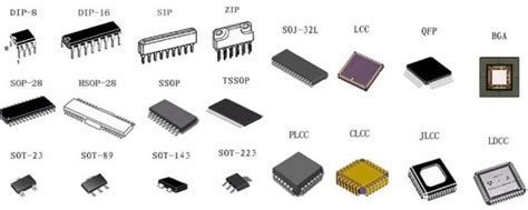
Common SMD Component Packages
There are numerous SMD component packages available, each with its own unique characteristics and applications. Some of the most common packages include:
1. Resistors
Chip Resistors
| Package | Dimensions (mm) | Power Rating (W) |
|---|---|---|
| 0201 | 0.6 x 0.3 | 0.05 |
| 0402 | 1.0 x 0.5 | 0.063 |
| 0603 | 1.6 x 0.8 | 0.1 |
| 0805 | 2.0 x 1.2 | 0.125 |
| 1206 | 3.2 x 1.6 | 0.25 |
Chip resistors are the most common type of SMD resistor. They are rectangular in shape and have a ceramic substrate with a resistive material deposited on top. The resistance value is indicated by a numerical code printed on the component.
MELF (Metal Electrode Leadless Face) Resistors
MELF resistors are cylindrical in shape and have a higher power rating compared to chip resistors. They are often used in high-power applications or where high precision is required.
2. Capacitors
Ceramic Chip Capacitors
| Package | Dimensions (mm) | Capacitance Range (pF) |
|---|---|---|
| 0201 | 0.6 x 0.3 | 0.1 – 100 |
| 0402 | 1.0 x 0.5 | 1 – 10,000 |
| 0603 | 1.6 x 0.8 | 1 – 100,000 |
| 0805 | 2.0 x 1.2 | 1 – 1,000,000 |
| 1206 | 3.2 x 1.6 | 1 – 10,000,000 |
Ceramic chip capacitors are the most common type of SMD capacitor. They are rectangular in shape and have a ceramic dielectric material sandwiched between two metal electrodes. The capacitance value is indicated by a numerical code printed on the component.
Tantalum Capacitors
Tantalum capacitors are polarized capacitors that offer high capacitance values in a small package. They are often used in power supply filtering and decoupling applications. Tantalum capacitors are available in both solid and electrolytic types.
3. Inductors
Chip Inductors
Chip inductors are rectangular in shape and have a ceramic or ferrite core with a wire wound around it. They are available in various sizes and inductance values, making them suitable for a wide range of applications, such as RF circuits and power supply filtering.
Wirewound Inductors
Wirewound inductors have a higher current carrying capacity compared to chip inductors. They consist of a wire wound around a ferrite or ceramic core and are often used in power supply and filtering applications.
4. Integrated Circuits (ICs)
Small Outline Integrated Circuit (SOIC)
SOIC packages are rectangular in shape and have leads extending from two sides of the component. They are available in various lead counts, such as 8, 14, 16, and 20 leads. SOICs are commonly used for analog and digital ICs, such as operational amplifiers, microcontrollers, and memory devices.
Quad Flat Pack (QFP)
QFP packages are square in shape and have leads extending from all four sides of the component. They are available in various lead counts, ranging from 32 to 256 leads. QFPs are commonly used for microprocessors, microcontrollers, and other complex digital ICs.
Ball Grid Array (BGA)
BGA packages have a grid of solder balls on the bottom of the component, allowing for a high density of interconnects. They are commonly used for high-performance ICs, such as graphics processors, field-programmable gate arrays (FPGAs), and application-specific integrated circuits (ASICs).

Identifying SMD Components
Identifying SMD components can be challenging due to their small size and the variety of packages available. However, there are several methods that can be used to accurately identify these components:
1. Visual Inspection
The first step in identifying an SMD component is to visually inspect it. Look for any markings or codes printed on the component that can provide information about its type, value, or manufacturer. Many SMD components have standardized markings that follow industry conventions, such as the EIA-96 standard for chip resistors and capacitors.
2. Reference Tables and Datasheets
Once you have identified the markings on the component, you can use reference tables or datasheets to determine its specific characteristics. Many manufacturers provide detailed datasheets for their SMD components, which include information such as package dimensions, electrical specifications, and recommended soldering profiles.
3. Measurement Techniques
In some cases, visual inspection and reference tables may not provide enough information to accurately identify an SMD component. In these situations, measurement techniques can be used to determine the component’s electrical characteristics.
Resistance Measurement
For resistors, a Multimeter can be used to measure the resistance value directly. Set the multimeter to the appropriate resistance range and place the probes on the component’s terminals.
Capacitance Measurement
For capacitors, a capacitance meter or an LCR meter can be used to measure the capacitance value. Some multimeters also have a capacitance measurement function.
Inductance Measurement
For inductors, an LCR meter is typically used to measure the inductance value. Some multimeters may also have an inductance measurement function, although this is less common.

Common SMD Component Markings and Codes
Understanding the markings and codes used on SMD components is essential for accurate identification. Here are some common marking conventions:
Resistors
Chip resistors often use a three or four-digit numerical code to indicate their resistance value and tolerance. The EIA-96 standard provides a table for converting these codes to actual resistance values.
For example, a chip resistor with the code “103” would have a resistance value of 10 × 10^3 ohms, or 10 kΩ, with a tolerance of ±5%.
Capacitors
Ceramic chip capacitors use a similar coding system to indicate their capacitance value and tolerance. The first two digits represent the first two significant digits of the capacitance value, while the third digit represents the multiplier (number of zeros).
For example, a ceramic chip capacitor with the code “104” would have a capacitance value of 10 × 10^4 picofarads, or 100 nF, with a tolerance of ±10%.
Inductors
Inductor markings often include the inductance value and tolerance, along with the manufacturer’s part number or code.
Integrated Circuits
ICs typically have a part number printed on the top of the component, which can be used to identify the specific device and its function. Manufacturer logos and date codes may also be present.

Frequently Asked Questions (FAQ)
1. What does SMD stand for?
SMD stands for Surface Mount Device. It refers to electronic components that are designed to be mounted directly onto the surface of a printed circuit board (PCB).
2. What are the advantages of using SMD components?
SMD components offer several advantages, including smaller size, faster assembly processes, increased circuit density, improved high-frequency performance, and lower cost for high-volume production.
3. How do I identify an SMD resistor’s value?
To identify an SMD resistor’s value, look for a three or four-digit numerical code printed on the component. This code follows the EIA-96 standard and can be converted to the actual resistance value using a reference table.
4. What is the difference between a chip capacitor and a tantalum capacitor?
Chip capacitors are non-polarized and have a ceramic dielectric, while tantalum capacitors are polarized and offer high capacitance values in a small package. Tantalum capacitors are often used in power supply filtering and decoupling applications.
5. How can I determine the specific function of an SMD integrated circuit?
To determine the specific function of an SMD integrated circuit, look for the part number printed on the top of the component. This part number can be used to find the corresponding datasheet, which will provide detailed information about the device’s function, electrical specifications, and application notes.
No responses yet