Introduction to AC-DC Converters
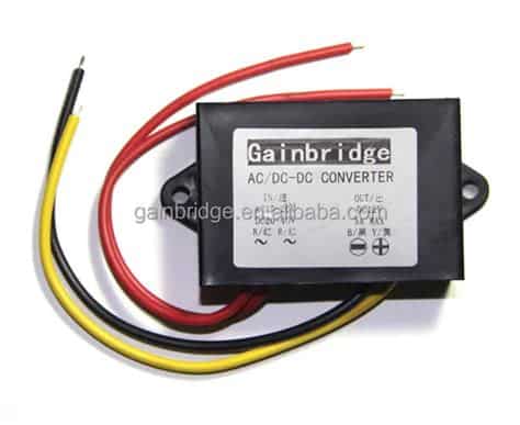
An AC-DC converter, also known as a rectifier, is an electronic circuit that converts alternating current (AC) to direct current (DC). AC-DC converters are essential in many electronic devices, including power supplies, battery chargers, and household appliances. They allow these devices to operate using the AC power from wall outlets while powering their internal components with DC.
Types of AC-DC Converters
There are several types of AC-DC converters, each with its own advantages and disadvantages. The most common types are:
- Half-wave rectifier
- Full-wave rectifier
- Center-tapped full-wave rectifier
- Bridge rectifier
- Switched-mode power supply (SMPS)
Half-Wave Rectifier
A half-wave rectifier is the simplest type of AC-DC converter. It uses a single diode to allow current to flow in only one direction, effectively cutting off half of the AC waveform. While simple and inexpensive, half-wave rectifiers have high ripple voltage and low efficiency.
Full-Wave Rectifier
Full-wave rectifiers use multiple diodes to convert both the positive and negative halves of the AC waveform into pulsating DC. There are two main types of full-wave rectifiers:
- Center-tapped full-wave rectifier: Uses a transformer with a center tap on the secondary winding and two diodes.
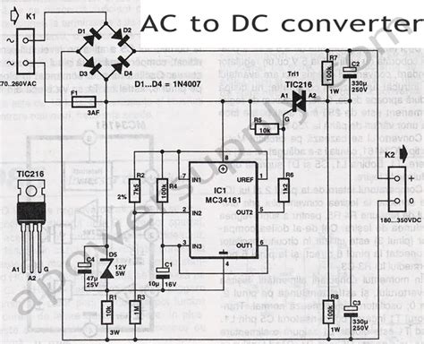
- Bridge rectifier: Uses four diodes arranged in a bridge configuration, eliminating the need for a center-tapped transformer.
Full-wave rectifiers have lower ripple voltage and higher efficiency compared to half-wave rectifiers.
Switched-Mode Power Supply (SMPS)
A switched-mode power supply is a more advanced type of AC-DC converter that uses high-frequency switching to regulate the output voltage. SMPSs are highly efficient and can provide multiple output voltages. They are commonly used in computer power supplies, mobile phone chargers, and other high-power applications.
Designing an AC-DC Converter in Altium Designer
Altium Designer is a powerful electronic design automation (EDA) software for designing printed circuit boards (PCBs) and electronic circuits. In this section, we will walk through the steps to design a basic full-wave bridge rectifier AC-DC converter in Altium Designer.
Step 1: Create a New Project
- Open Altium Designer and create a new project by clicking on “File” > “New” > “Project.”
- Give your project a name and choose a location to save it.
- Select “PCB Project” as the project type and click “OK.”
Step 2: Create a New Schematic
- In the Projects panel, right-click on your project and select “Add New to Project” > “Schematic.”
- Give your schematic a name and click “OK.”
Step 3: Add Components
- Press “P” to open the Libraries panel.
- Search for the following components and place them on the schematic:
- 4 diodes (e.g., 1N4007)
- 1 transformer (choose an appropriate rating for your application)
- 1 capacitor (choose an appropriate value for your desired ripple voltage)
- 1 load resistor (represents the device being powered)
- Arrange the components neatly on the schematic.
Step 4: Wire the Components
- Use the “Place Wire” tool to connect the components as follows:
- Connect the AC input to the primary winding of the transformer.
- Connect the secondary winding of the transformer to the four diodes, arranged in a bridge configuration.
- Connect the positive output of the bridge to the positive terminal of the capacitor and load resistor.
- Connect the negative output of the bridge to the negative terminal of the capacitor and load resistor.
- Label the wires and components as necessary for clarity.
Step 5: Set Component Values
- Double-click on each component to open its properties window.
- Set the appropriate values for the transformer, capacitor, and load resistor based on your design requirements.
Step 6: Run a Simulation
- Go to “Tools” > “Simulate” > “Mixed Sim.”
- Set up the simulation parameters, such as the AC input voltage and frequency.
- Run the simulation and analyze the output waveforms to ensure the circuit is functioning as expected.
Step 7: Design the PCB
- Switch to the PCB editor by clicking on the “PCB” tab at the bottom of the screen.
- Use the “Import Changes” tool to update the PCB with the schematic changes.
- Arrange the components on the PCB and route the traces.
- Add any necessary silkscreen labels and markers.
- Run design rule checks (DRC) to ensure the PCB meets manufacturing requirements.
Step 8: Generate Manufacturing Files
- Go to “File” > “Fabrication Outputs” > “Gerber Files.”
- Set up the Gerber file generation options and click “OK” to generate the files.
- Send the Gerber files to a PCB manufacturer for production.
AC-DC Converter Design Considerations
When designing an AC-DC converter, there are several key factors to consider to ensure optimal performance and reliability:
Input Voltage and Frequency
The input voltage and frequency of the AC source must be compatible with the transformer and other components in the circuit. Common input voltages include 120V and 240V, with frequencies of 50Hz or 60Hz.
Output Voltage and Current
The desired output voltage and current of the AC-DC converter must be determined based on the requirements of the load device. The transformer, diodes, and capacitor must be selected to handle the expected output power.
Ripple Voltage
Ripple voltage is the residual AC component present in the DC output of the converter. A larger filter capacitor can help reduce the ripple voltage, but it also increases the size and cost of the circuit. The acceptable level of ripple voltage depends on the sensitivity of the load device.
Efficiency
The efficiency of an AC-DC converter is the ratio of output power to input power, expressed as a percentage. Higher efficiency means less power is wasted as heat, which is important for reducing energy costs and preventing overheating. The choice of components and circuit topology can significantly impact efficiency.
Safety and Isolation
AC-DC converters must provide adequate isolation between the AC input and DC output to prevent electric shock hazards. This is typically achieved using a transformer with appropriate insulation and creepage distances. The circuit must also include fuses or other overcurrent protection devices to prevent damage in case of a fault.

FAQs
Q1: What is the difference between a half-wave and full-wave rectifier?
A: A half-wave rectifier uses a single diode to convert only one half of the AC waveform to DC, resulting in high ripple voltage and low efficiency. A full-wave rectifier uses multiple diodes to convert both halves of the AC waveform, providing lower ripple voltage and higher efficiency.
Q2: What is the purpose of the filter capacitor in an AC-DC converter?
A: The filter capacitor helps to smooth out the pulsating DC output from the rectifier, reducing the ripple voltage and providing a more stable DC voltage to the load device.
Q3: How do I select the appropriate transformer for my AC-DC converter?
A: When selecting a transformer, consider the following factors:
– Input voltage and frequency
– Output voltage and current
– Power rating
– Insulation and safety requirements
Consult the transformer manufacturer’s datasheets and application notes for guidance on selecting the appropriate model for your design.
Q4: What are some common applications of AC-DC converters?
A: AC-DC converters are used in a wide range of applications, including:
– Power supplies for electronic devices
– Battery chargers
– Home appliances
– Industrial equipment
– Telecommunications systems
– Automotive electronics
Q5: Can I use Altium Designer to simulate my AC-DC converter design?
A: Yes, Altium Designer includes a built-in mixed-signal circuit simulator called Mixed Sim. You can use Mixed Sim to simulate your AC-DC converter design and analyze the output waveforms to verify its performance before building a physical prototype.
Conclusion
Designing an AC-DC converter in Altium Designer involves creating a schematic, selecting appropriate components, simulating the circuit, and designing the PCB. By following the step-by-step process outlined in this article and considering the key design factors, you can create a reliable and efficient AC-DC converter for your specific application.
Remember to always prioritize safety and adhere to relevant standards and regulations when working with AC power. With the powerful tools and features provided by Altium Designer, you can streamline your AC-DC converter design process and bring your projects to life more quickly and efficiently.
No responses yet