Introduction to 4-20mA Current Loops
A 4-20mA current loop is a widely used standard in industrial control and monitoring systems. It allows for the transmission of analog signals over long distances with high noise immunity. The current loop transmitter sends a signal ranging from 4mA to 20mA, representing the minimum and maximum values of the measured parameter, respectively. The receiver, on the other hand, converts this current signal back into a voltage or digital value that can be processed by a controller or monitoring system.
In this article, we will discuss how to design a simple and cost-effective 4-20mA current loop receiver using minimal components. We will cover the basic principles of current loop receivers, the required components, and step-by-step instructions for building and testing the circuit.
Understanding Current Loop Receivers
Principles of Operation
A current loop receiver works by converting the 4-20mA current signal into a voltage that can be easily measured or processed. The most common method for achieving this is by using a precision resistor to convert the current into a voltage drop across the resistor. The value of the resistor is chosen such that the voltage drop corresponds to a standard voltage range, typically 1-5V or 0-10V.
The relationship between the current and voltage is governed by Ohm’s law:
V = I × R
Where:
– V is the voltage drop across the resistor (in volts)
– I is the current flowing through the resistor (in amperes)
– R is the resistance of the precision resistor (in ohms)
Benefits of Current Loop Signals
Current loop signals offer several advantages over voltage signals, making them ideal for industrial applications:
- Long-distance transmission: Current loops can transmit signals over distances up to 1000 meters without significant signal degradation.
- Noise immunity: Current loops are less susceptible to electromagnetic interference and noise compared to voltage signals.
- Simple wiring: Current loops require only two wires for signal transmission, simplifying installation and maintenance.
- Fail-safe operation: A broken wire or open circuit in a current loop system can be easily detected, as the current will drop to zero.
Designing a 4-20mA Current Loop Receiver
Required Components
To build a simple 4-20mA current loop receiver, you will need the following components:
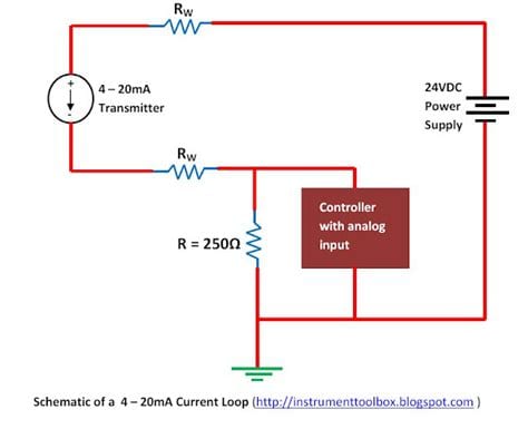
- Precision resistor (e.g., 250Ω for a 1-5V output)
- Operational amplifier (e.g., LM358 or similar)
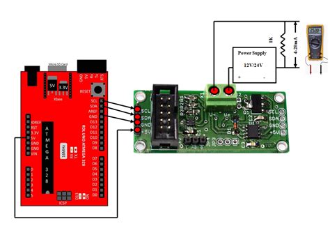
- Power supply (e.g., 24VDC)
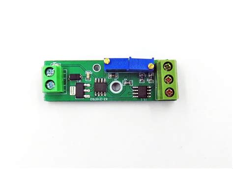
- Terminal block or screw terminals for connections
- PCB or breadboard for prototyping
Circuit Design
The circuit design for a basic 4-20mA current loop receiver consists of two main parts: the precision resistor and the operational amplifier.
- Precision resistor:
- The resistor converts the 4-20mA current into a voltage drop.
- The value of the resistor determines the output voltage range.
-
For a 1-5V output, use a 250Ω resistor (5V / 20mA = 250Ω).
-
Operational amplifier:
- The op-amp is used as a buffer to provide a low-impedance output.
- It ensures that the output voltage is not affected by the load connected to the receiver.
- The non-inverting configuration is used, with the precision resistor connected between the inverting input and ground.
Here’s a simple schematic of the 4-20mA current loop receiver circuit:
           +24V
            |
            |
           +-+
           | |
           | | 250Ω
           | |
           +-+
            |
            +---+---+
                |   |
                |   |
                +---+
                |   |
                |   +--+
                |      |
                +------+
                |
                | +
            +---+---+
            |   -   |
            | LM358 |
            |       |
            +---+---+
                |
                |
               +++
              +   +
             +     +
            +       +
           +         +
          +           +
         +             +
        +               +
       +                 +
      +                   +
     +                     +
    +                       +
   +                         +
  +                           +
 +                             +
+                               +
|                               |
|                               |
+-------------------------------+
                |
                |
                +-----+
                      |
                      |
                      +----  Output (1-5V)
Step-by-Step Assembly
- Begin by gathering all the required components and tools.
- If using a PCB, solder the precision resistor and the op-amp to the board according to the schematic. If using a breadboard, insert the components into the appropriate slots.
- Connect the positive terminal of the 24VDC power supply to one end of the precision resistor.
- Connect the other end of the precision resistor to the inverting input (pin 2) of the op-amp and to one of the input terminals of the current loop.
- Connect the non-inverting input (pin 3) of the op-amp to ground.
- Connect the output (pin 1) of the op-amp to the output terminal of the receiver.
- Connect the negative terminal of the 24VDC power supply to the other input terminal of the current loop and to the ground.
Testing and Calibration
Once the circuit is assembled, it’s essential to test and calibrate the current loop receiver to ensure accurate readings.
- Apply power to the circuit and verify that the op-amp is receiving the correct supply voltage.
- Connect a current source (4-20mA) to the input terminals of the receiver.
- Measure the voltage at the output terminal using a digital multimeter.
- Adjust the current source to 4mA and verify that the output voltage is approximately 1V (4mA × 250Ω = 1V).
- Adjust the current source to 20mA and verify that the output voltage is approximately 5V (20mA × 250Ω = 5V).
- If the output voltage is not within the expected range, recheck the circuit connections and component values.

Conclusion
Designing a 4-20mA current loop receiver with minimal components is a straightforward process that can be accomplished using a precision resistor and an operational amplifier. By following the steps outlined in this article, you can build a reliable and cost-effective receiver for your industrial control or monitoring application.
Remember to always exercise caution when working with electrical circuits and follow proper safety guidelines. If you are unsure about any aspect of the design or assembly process, consult with a qualified professional or refer to the manufacturer’s documentation for your specific components.
FAQ
- What is the purpose of a 4-20mA current loop receiver?
-
A 4-20mA current loop receiver converts a 4-20mA current signal into a voltage that can be easily measured or processed by a controller or monitoring system.
-
Can I use a different value resistor for the precision resistor?
-
Yes, you can use a different value resistor, but it will change the output voltage range. For example, using a 500Ω resistor will result in a 2-10V output range.
-
Is it necessary to use an operational amplifier in the circuit?
-
While not strictly necessary, using an op-amp as a buffer provides a low-impedance output and ensures that the output voltage is not affected by the load connected to the receiver.
-
Can I power the circuit with a different voltage supply?
-
Yes, you can use a different voltage supply, but ensure that it is compatible with the op-amp and provides sufficient headroom for the desired output voltage range.
-
How do I troubleshoot if the output voltage is not within the expected range?
- First, verify that the circuit is properly assembled and that all connections are secure. Then, recheck the component values and ensure that the current source is providing the correct input signal. If the issue persists, consult the manufacturer’s documentation for your specific components or seek assistance from a qualified professional.
References
- “4-20mA Current Loop Primer” by ADI – https://www.analog.com/media/en/training-seminars/tutorials/MT-022.pdf
- “Designing 4-20mA Current Loop Applications” by Maxim Integrated – https://www.maximintegrated.com/en/design/technical-documents/tutorials/1/1869.html
- “4-20mA Current Loop Circuit Design” by Circuit Basics – https://www.circuitbasics.com/4-20ma-current-loop-circuit-design/
Keyword-Rich Subheadings
H2: Understanding the Basics of 4-20mA Current Loops
H3: What is a 4-20mA Current Loop?
H3: Advantages of Using 4-20mA Current Loops
H3: Applications of 4-20mA Current Loops
H2: Components Required for a 4-20mA Current Loop Receiver
H3: Precision Resistor Selection
H3: Operational Amplifier Choice
H3: Power Supply Considerations
H2: Step-by-Step Guide to Building a 4-20mA Current Loop Receiver
H3: Circuit Schematic and Design
H3: PCB Layout and Assembly
H3: Testing and Calibration Procedure
H2: Troubleshooting Common Issues with 4-20mA Current Loop Receivers
H3: Incorrect Output Voltage Range
H3: Noise and Interference Problems
H3: Component Failure and Replacement
Table: Resistor Values for Common Output Voltage Ranges
| Output Voltage Range | Precision Resistor Value |
|---|---|
| 1-5V | 250Ω |
| 0-5V | 250Ω |
| 0-10V | 500Ω |
| 2-10V | 400Ω |
This table provides a quick reference for selecting the appropriate precision resistor value based on the desired output voltage range of the 4-20mA current loop receiver.
No responses yet