Introduction to High Frequency PCB Materials
When designing printed circuit boards (PCBs) for high frequency applications, material selection is critical. The choice of PCB substrate material directly impacts the electrical performance, signal integrity, and reliability of the final product. This article explores the key considerations and best practices for selecting PCB materials suitable for high frequency designs.
What are High Frequency PCBs?
High frequency PCBs are specialized circuit boards designed to operate at high frequencies, typically above 100 MHz. These PCBs are used in applications such as:
- RF and microwave circuits
- Wireless communication systems
- Radar and satellite technology
- High-speed digital devices
At high frequencies, the behavior of signals on the PCB becomes more complex due to factors such as signal loss, dielectric loss, and impedance mismatches. Therefore, the choice of PCB material is crucial to ensure optimal performance.
Key Properties of High Frequency PCB Materials
When selecting materials for high frequency PCBs, several key properties need to be considered:
1. Dielectric Constant (Dk)
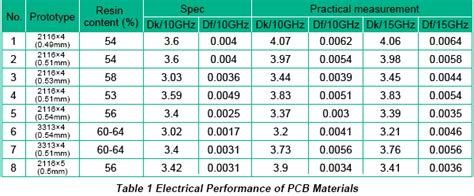
The dielectric constant, also known as relative permittivity (εr), is a measure of a material’s ability to store electrical energy. In high frequency PCBs, a lower dielectric constant is generally preferred as it allows for faster signal propagation and reduced signal delay. Common high frequency PCB materials and their dielectric constants are listed in the table below:
| Material | Dielectric Constant (Dk) |
|---|---|
| FR-4 | 4.2 – 4.5 |
| Rogers RO4003C | 3.38 |
| Rogers RO4350B | 3.48 |
| Isola I-Tera MT40 | 3.45 |
| Taconic RF-35 | 3.50 |
2. Dissipation Factor (Df)
The dissipation factor, also known as loss tangent (tanδ), represents the amount of energy lost as heat in the dielectric material. A lower dissipation factor is desirable for high frequency PCBs to minimize signal loss and maintain signal integrity. The table below compares the dissipation factors of common high frequency PCB materials:
| Material | Dissipation Factor (Df) |
|---|---|
| FR-4 | 0.02 |
| Rogers RO4003C | 0.0027 |
| Rogers RO4350B | 0.0037 |
| Isola I-Tera MT40 | 0.0028 |
| Taconic RF-35 | 0.0033 |
3. Thermal Coefficient of Dielectric Constant (TCDk)
The thermal coefficient of dielectric constant (TCDk) represents the change in dielectric constant with temperature. A stable TCDk is important to ensure consistent performance across the operating temperature range of the PCB. Materials with low TCDk values are preferred for high frequency applications.
4. Copper Foil Roughness
The roughness of the copper foil used in the PCB can impact high frequency performance. Smoother copper foils are generally preferred as they minimize Skin Effect losses and provide better signal integrity. The table below compares the roughness of different copper foil types:
| Copper Foil Type | Roughness (μm RMS) |
|---|---|
| Standard (STD) | 0.8 – 1.8 |
| Very Low Profile (VLP) | 0.3 – 0.6 |
| Ultra Low Profile (ULP) | 0.15 – 0.3 |
5. Thermal Conductivity
Thermal conductivity is the ability of a material to conduct heat. In high frequency PCBs, good thermal conductivity helps dissipate heat generated by components and prevents thermal issues that can affect performance and reliability. Materials with higher thermal conductivity are preferred for heat-sensitive applications.

PCB Material Categories
High frequency PCB materials can be broadly categorized into three main groups:
1. FR-4 and Enhanced FR-4
FR-4 is the most widely used PCB material due to its low cost and good mechanical properties. However, standard FR-4 has limitations in high frequency applications due to its relatively high dielectric constant and dissipation factor. Enhanced FR-4 materials, such as Isola TerraGreen or Nan Ya NH-180, offer improved high frequency performance compared to standard FR-4.
2. PTFE-based Materials
PTFE (polytetrafluoroethylene) based materials, such as Rogers RT/duroid and Taconic TLY, are popular choices for high frequency PCBs. These materials offer low dielectric constant, low dissipation factor, and excellent thermal stability. However, PTFE-based materials are more expensive and have lower mechanical strength compared to FR-4.
3. Ceramic-filled Hydrocarbon Materials
Ceramic-filled hydrocarbon materials, such as Rogers RO4000 series and Isola I-Tera, provide a balance between the cost and performance of FR-4 and PTFE-based materials. These materials offer lower dielectric constant and dissipation factor than FR-4, along with good mechanical properties and thermal stability.

Best Practices for High Frequency PCB Material Selection
When selecting materials for high frequency PCBs, consider the following best practices:
-
Understand the application requirements: Clearly define the operating frequency, bandwidth, signal integrity, and environmental conditions of the PCB to guide material selection.
-
Prioritize low dielectric constant and dissipation factor: Choose materials with low Dk and Df values to minimize signal loss and maintain signal integrity at high frequencies.
-
Consider thermal stability: Select materials with stable thermal properties, such as low TCDk, to ensure consistent performance over the operating temperature range.
-
Evaluate copper foil roughness: Opt for smoother copper foils, such as VLP or ULP, to minimize skin effect losses and improve signal integrity.
-
Balance cost and performance: Consider the trade-offs between material cost and performance based on the specific application requirements and budget constraints.
-
Collaborate with PCB manufacturers: Work closely with experienced PCB manufacturers who have expertise in high frequency materials and can provide guidance on material selection and PCB design.

FAQ
Q1: What is the difference between dielectric constant (Dk) and dissipation factor (Df)?
A1: Dielectric constant (Dk) represents a material’s ability to store electrical energy, while dissipation factor (Df) represents the amount of energy lost as heat in the dielectric material. A lower Dk allows for faster signal propagation, and a lower Df minimizes signal loss.
Q2: Can FR-4 be used for high frequency PCBs?
A2: Standard FR-4 has limitations in high frequency applications due to its relatively high dielectric constant and dissipation factor. However, enhanced FR-4 materials with improved high frequency performance, such as Isola TerraGreen or Nan Ya NH-180, can be used in some high frequency designs.
Q3: What are the advantages of PTFE-based materials for high frequency PCBs?
A3: PTFE-based materials, such as Rogers RT/duroid and Taconic TLY, offer low dielectric constant, low dissipation factor, and excellent thermal stability, making them well-suited for high frequency applications. However, they are more expensive and have lower mechanical strength compared to FR-4.
Q4: How does copper foil roughness affect high frequency performance?
A4: Smoother copper foils, such as VLP (Very Low Profile) or ULP (Ultra Low Profile), are generally preferred for high frequency PCBs as they minimize skin effect losses and provide better signal integrity compared to standard copper foils with higher roughness.
Q5: What should I consider when selecting materials for high frequency PCBs?
A5: When selecting materials for high frequency PCBs, consider factors such as the application requirements, dielectric constant, dissipation factor, thermal stability, copper foil roughness, cost, and performance trade-offs. Collaborate with experienced PCB manufacturers for guidance on material selection and PCB design.
Conclusion
Selecting the right materials for high frequency PCBs is crucial to ensure optimal performance, signal integrity, and reliability. By understanding the key properties of high frequency PCB materials, such as dielectric constant, dissipation factor, thermal stability, and copper foil roughness, designers can make informed decisions when choosing materials for their specific applications.
Following best practices, such as prioritizing low dielectric constant and dissipation factor, considering thermal stability, evaluating copper foil roughness, and balancing cost and performance, can help in selecting the most suitable materials for high frequency PCBs.
It is essential to collaborate with experienced PCB manufacturers who have expertise in high frequency materials and can provide valuable guidance on material selection and PCB design. By carefully considering the material properties and application requirements, designers can create high-performance high frequency PCBs that meet the demands of today’s advanced electronic systems.

No responses yet