Introduction to Hartley Oscillators
Hartley oscillators are a type of electronic oscillator circuit that is commonly used to generate sine wave signals. They were invented by American engineer Ralph V.L. Hartley in 1915 while he was working at the Western Electric Company.
The key feature of Hartley oscillators is their ability to maintain a constant amplitude output signal, even under varying load conditions. This makes them an excellent choice for applications that require a stable, reliable oscillation source.
How Hartley Oscillators Work
At its core, a Hartley oscillator consists of a resonant LC tank circuit and an amplifier. The tank circuit determines the frequency of oscillation, while the amplifier compensates for losses in the tank circuit to sustain the oscillations.
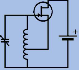
Here is a simplified schematic of a Hartley oscillator:
[Hartley oscillator schematic diagram]
The tank circuit is made up of an inductor (L) and a capacitor (C). The inductor is tapped, meaning a connection is made partway through its coils. This splits the inductor into two parts (L1 and L2 in the diagram).
The amplifier is usually a single transistor. The emitter of the transistor connects to the tap point on the inductor. Positive feedback from the collector is fed back to the base of the transistor through the capacitor.
When power is applied, any small noise will be amplified by the transistor. The amplified signal appears at the collector. The LC circuit starts to resonate at its natural resonant frequency, as determined by the values of L and C:
f = 1 / (2π√LC)
The signal from the collecter is fed back to the base with the correct phase to reinforce the oscillations. The oscillations rapidly build up until they reach a stable amplitude where the amplifier gain equals the losses in the tank circuit.
Advantages of Hartley Oscillators
Hartley oscillators have several advantages compared to other types of oscillator circuits:
- Simplicity – they require few components and are easy to design and construct
- Good frequency stability – the resonant frequency is determined by high-quality inductors and capacitors
- Excellent amplitude stability – the oscillation amplitude remains constant even with changes in load, supply voltage, etc.
- Low distortion sine wave output
- Relatively immune to Stray Capacitance effects
These factors make Hartley oscillators a popular choice for applications like RF signal generation, test equipment, local oscillators in radio receivers, etc.
Designing Hartley Oscillators
Selecting L and C Values
The first step in designing a Hartley oscillator is selecting appropriate values for the inductor and capacitor in the resonant tank. The L and C values determine the frequency of oscillation, so they must be chosen to give the desired frequency.
As shown in the formula above, oscillation frequency is inversely proportional to the square root of the L-C product. So larger L and C values give a lower frequency.
Here is a table showing some typical L-C combinations for common oscillation frequencies:
| Frequency | Inductance (L) | Capacitance (C) |
|---|---|---|
| 100 kHz | 100 μH | 2.5 nF |
| 1 MHz | 10 μH | 250 pF |
| 10 MHz | 1 μH | 25 pF |
The inductor’s tap point location also affects oscillator performance. The ratio of turns between L1 and L2 sets the amount of feedback. More turns in L1 compared to L2 gives more feedback. A typical ratio is around 4:1 (80% of turns in L1, 20% in L2).
Transistor Selection and Biasing
The transistor used in a Hartley oscillator must have sufficient gain at the oscillation frequency to overcome tank circuit losses. It also needs to handle the expected power dissipation.
For low frequencies (up to a few MHz), general purpose NPN bipolartransistors like the 2N3904 are a good choice. For higher frequencies, RF transistors or even FETs may be required.
The transistor also needs a suitable DC bias point for proper operation in the linear amplification region. Biasing involves setting the DC emitter, base, and collector voltages and currents.
A common biasing approach is shown here:
[Hartley oscillator schematic with biasing]
Resistor R1 and R2 form a voltage divider that sets the base bias voltage. RE is an emitter resistor that stabilizes the bias point against temperature variations. The Bypass Capacitor CE shunts any AC at the emitter to ground to prevent degenerative feedback.
The collector supply voltage VCC and resistor RC are chosen to give the desired collector current and power dissipation in the transistor.
Construction Tips
To achieve best performance, pay attention to good construction techniques:
- Keep component lead lengths short, especially at high frequencies
- Use a ground plane on the circuit board to reduce stray inductance and capacitance
- Physically separate the input and output to minimize unwanted coupling
- Include power supply decoupling capacitors to reduce noise
- Use high-quality, temperature-stable inductors and capacitors in the tank circuit
- Protect the circuit from overload and voltage spikes that could damage the transistor

Applications for Hartley Oscillators
Hartley oscillators are used in a variety of electronic applications, including:
RF Signal Sources
One of the most common uses for Hartley oscillators is generating RF carrier signals. The constant amplitude sine wave output is ideal for this purpose.
By making the tank inductor variable, the oscillation frequency can be adjusted. This allows generating precise frequencies for purposes like testing RF receivers, calibrating equipment, etc.
Hartley oscillators can be used to generate carrier signals over a wide range of frequencies, from low RF up to VHF and UHF. For higher frequencies, the tank capacitance may consist of just the stray capacitance of the circuit.
Local Oscillators
Hartley oscillators are often used as the local oscillator (LO) in superheterodyne radio receivers. The LO generates a signal which is mixed with the incoming radio signal to produce an intermediate frequency (IF) for further amplification and demodulation.
A variable frequency Hartley oscillator allows tuning the receiver to different stations. The constant amplitude LO signal helps maintain good mixing performance and minimizes pulling due to the aerial signal.
Morse Code Practice Oscillators
Another application for Hartley oscillators is in morse code practice oscillators. These are used by ham radio enthusiasts learning or practicing sending and receiving morse code.
A morse code practice oscillator generates an audio tone that is switched on and off by a telegraph key. A variable pitch Hartley audio oscillator produces a pleasant sine wave tone. The constant output amplitude maintains the tone quality as the key is operated.
Quartz Crystal Oscillators
For applications requiring very high frequency stability, a quartz crystal can be used in place of the LC tank circuit. Quartz crystals have a very high quality factor (Q) and exhibit an extremely stable resonant frequency.
A crystal-controlled Hartley oscillator can achieve frequency stabilities on the order of 1 ppm (part per million) or better. Temperature-compensated crystal oscillators (TCXOs) are used as frequency references in applications like GPS receivers, precision timekeeping, etc.

Troubleshooting Common Problems
While Hartley oscillators are relatively simple and robust, there are a few common issues that may be encountered:
Failure to Oscillate
The most common problem is a failure to oscillate at all. Potential causes include:
- Wiring error in the feedback connection from collector to base
- Transistor damaged or in backwards
- Insufficient transistor gain at the oscillation frequency
- L or C value too large or small for the transistor and supply voltage used
- Excessive loading on the tank circuit
- Shorted or open bypass capacitor
Double-check the wiring, component values, and Transistor Pinout and condition. Measure the DC bias voltages on the transistor. If all else looks good, try a higher gain transistor.
Incorrect Frequency
If the oscillator is running but at the wrong frequency, possible issues are:
- Incorrect L or C value for the desired frequency – double-check component values and calculations
- Additional stray capacitance or inductance affecting the tank circuit – keep leads short and components spaced apart
- Tank components not temperature stable – use high-quality NPO capacitors and stable inductors
- Different supply voltage than the circuit was designed for – changing VCC can pull the frequency
Poor Amplitude Stability
A Hartley oscillator that is working but has an output amplitude that varies may have:
- A bad connection or damaged component causing intermittent changes in gain
- Supply voltage fluctuations affecting the bias point – use well-regulated supply and decouple properly
- Excessive loading on the output – ensure the load impedance is high enough and consider buffering the output
- The transistor being overdriven into saturation – reduce the feedback ratio or RC

Frequently Asked Questions
What are the advantages of Hartley oscillators over other types?
Hartley oscillators offer several key advantages:
- Simple design with few components
- Very good frequency stability
- Excellent amplitude stability under varying conditions
- Pure sine wave output with low distortion
- Wide frequency range from low RF to UHF
These make Hartley oscillators an excellent choice for many electronic applications requiring a stable, low-distortion oscillation source.
How does a Hartley oscillator maintain a constant output amplitude?
The output amplitude of a Hartley oscillator is a function of the amplifier gain and the losses in the tank circuit. When the circuit is first powered on, any small noise is amplified by the transistor. This signal is fed back to the tank circuit, which starts to oscillate at its resonant frequency.
The oscillation amplitude builds up exponentially until it reaches a level where the amplifier gain equals the tank circuit losses. At this point, the amplitude stabilizes and remains constant.
Changes in factors like supply voltage or loading affect both the amplifier and tank simultaneously. An increase in amplifier gain is balanced by an increase in tank losses, so the amplitude remains stable.
How do you set the oscillation frequency of a Hartley oscillator?
The oscillation frequency of a Hartley oscillator is determined by the resonant frequency of its LC tank circuit. This is found from the formula:
f = 1 / (2π√LC)
Where:
– f is the frequency in Hertz
– L is the tank inductance in Henries
– C is the tank capacitance in Farads
To set the desired oscillation frequency, simply select L and C values that satisfy the equation. Larger L and C give a lower frequency, while smaller values give a higher frequency.
The inductor can be made variable for fine tuning. A variable capacitor can also be used for wider tuning range.
What are some common applications for Hartley oscillators?
Hartley oscillators are used in a variety of electronic applications, such as:
- RF signal sources and generators
- Local oscillators in radio receivers
- Morse code practice oscillators
- Audio tone generators
- Quartz crystal oscillators for frequency references
- Test and measurement equipment
- Hobby and educational electronic projects
Their simple design, low cost, and excellent stability make Hartley oscillators a popular choice for many different oscillator needs.
Are there any limitations or disadvantages to Hartley oscillators?
While Hartley oscillators have many benefits, there are a few potential limitations to be aware of:
- The frequency is not easily varied over a wide range, as it requires changing the inductor or capacitor
- They are not suitable for very high frequencies (above UHF), as stray capacitance becomes an issue
- Output power is limited by the transistor used, so they are not suitable for driving low impedance loads directly
- Frequency can be pulled by a reactive load, so buffering may be needed
- Careful physical construction is required for best stability, especially at high frequencies
In applications where these factors are a concern, other oscillator topologies like the Colpitts or Clapp may be preferred. But in general, Hartley oscillators offer excellent performance for a wide range of uses.
No responses yet