Introduction to Flyback Converters
A flyback converter is a type of isolated power converter that is widely used in various applications, ranging from low-power chargers to high-power industrial systems. It is known for its simplicity, low cost, and ability to provide isolation between the input and output. The flyback converter is based on the principle of energy storage in a transformer’s magnetic field and subsequent release of that energy to the output.
Key Features of Flyback Converters
- Isolated topology: Provides galvanic isolation between input and output
- Single switch: Simplifies the design and reduces component count
- Wide input voltage range: Capable of operating with a wide range of input voltages
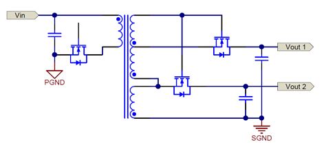
- Multiple outputs: Can provide multiple isolated outputs with a single transformer
- Low cost: Cost-effective solution for low to medium power applications
How Does a Flyback Converter Work?
Basic Operating Principle
The flyback converter operates in two distinct modes: the energy storage mode and the energy transfer mode. During the energy storage mode, the primary switch is turned on, allowing current to flow through the primary winding of the transformer. This current creates a magnetic field in the transformer, storing energy. The secondary diode is reverse-biased during this mode, preventing current flow in the secondary winding.
When the primary switch is turned off, the flyback converter enters the energy transfer mode. The magnetic field in the transformer collapses, inducing a voltage in the secondary winding. This voltage forward-biases the secondary diode, allowing current to flow to the output capacitor and load. The energy stored in the transformer during the previous mode is thus transferred to the output.
Continuous Conduction Mode (CCM) vs. Discontinuous Conduction Mode (DCM)
Flyback converters can operate in two different conduction modes: Continuous Conduction Mode (CCM) and Discontinuous Conduction Mode (DCM).
In CCM, the current in the primary winding never reaches zero during the switching cycle. This means that there is always some residual energy stored in the transformer when the next switching cycle begins. CCM operation is typically used in high-power applications where the output current is relatively large.
In DCM, the current in the primary winding reaches zero before the end of each switching cycle. This means that all the energy stored in the transformer is completely transferred to the output during each cycle. DCM operation is commonly used in low-power applications where the output current is relatively small.
The choice between CCM and DCM depends on the specific requirements of the application, such as output power, efficiency, and transient response.

Key Components of a Flyback Converter
Transformer
The transformer is the heart of the flyback converter. It provides isolation between the input and output and stores energy in its magnetic field during the energy storage mode. The transformer’s primary winding is connected to the input voltage through the primary switch, while the secondary winding is connected to the output through the secondary diode.
Primary Switch
The primary switch is responsible for controlling the flow of current in the primary winding of the transformer. It is typically a MOSFET (Metal-Oxide-Semiconductor Field-Effect Transistor) or an IGBT (Insulated-Gate Bipolar Transistor), depending on the power level and switching frequency of the converter.
Secondary Diode
The secondary diode rectifies the voltage induced in the secondary winding of the transformer during the energy transfer mode. It ensures that current flows only from the transformer to the output capacitor and load, preventing reverse current flow.
Output Capacitor
The output capacitor filters the rectified voltage from the secondary diode and provides a smooth DC output voltage to the load. It also stores energy to maintain the output voltage during the energy storage mode when no current is flowing in the secondary winding.
Controller
The controller is responsible for generating the switching signals for the primary switch. It monitors the output voltage and adjusts the switching duty cycle to maintain a constant output voltage under varying load conditions. The controller can be implemented using a dedicated integrated circuit (IC) or a microcontroller with appropriate firmware.

Flyback Converter Design Considerations
Transformer Design
The transformer is a critical component in the flyback converter, and its design significantly impacts the converter’s performance. The transformer’s primary and secondary windings must be chosen to provide the desired voltage conversion ratio and handle the required currents. The transformer’s magnetizing inductance determines the energy storage capability and affects the converter’s operating mode (CCM or DCM).
Snubber Circuit
In practical flyback converters, the leakage inductance of the transformer can cause high-voltage spikes across the primary switch during the turn-off process. These voltage spikes can damage the switch and cause electromagnetic interference (EMI). To mitigate this problem, a snubber circuit is often added to the primary side of the transformer. The snubber circuit absorbs the energy stored in the leakage inductance and limits the voltage spike across the switch.
Output Voltage Regulation
Flyback converters require a closed-loop control system to regulate the output voltage. The controller monitors the output voltage and adjusts the switching duty cycle to maintain a constant voltage under varying load conditions. There are two common control methods used in flyback converters:
-
Voltage-mode control: The controller monitors the output voltage directly and adjusts the duty cycle based on the voltage error signal.
-
Current-mode control: The controller monitors both the output voltage and the primary switch current. It uses the primary current as an additional control variable to improve the converter’s transient response and provide overcurrent protection.
Efficiency Optimization
Flyback converters can achieve high efficiency, but several factors must be considered to optimize their performance. These include:
- Choosing components with low losses (e.g., low on-resistance switches, low forward-voltage diodes)
- Minimizing transformer leakage inductance and winding resistance
- Operating the converter in the appropriate conduction mode (CCM or DCM) based on the load conditions
- Implementing synchronous rectification to replace the secondary diode with a low-resistance switch
- Optimizing the switching frequency to balance switching losses and component sizes

Applications of Flyback Converters
Flyback converters are used in a wide range of applications due to their simplicity, low cost, and isolation capabilities. Some common applications include:
Power Adapters and Chargers
Flyback converters are commonly used in low-power AC-DC adapters and chargers for electronic devices such as smartphones, laptops, and tablets. They provide the necessary voltage conversion and isolation while maintaining a compact form factor.
Power Supplies for Appliances
Many household appliances, such as televisions, set-top boxes, and audio equipment, use flyback converters in their power supply units. The flyback topology offers a cost-effective solution for providing the required isolated voltages to various parts of the appliance.
Industrial Power Supplies
Flyback converters are also used in industrial power supplies for applications such as process control, automation, and instrumentation. They provide isolated voltages to power sensors, actuators, and control circuits while ensuring reliable operation in harsh industrial environments.
Renewable Energy Systems
In renewable energy systems, such as solar photovoltaic (PV) and wind power systems, flyback converters are used as intermediate stages to provide isolation and voltage matching between the energy source and the load. They help in optimizing the power extraction from the renewable source and ensure safe operation of the connected equipment.
Advantages and Limitations of Flyback Converters
Advantages
- Simple topology with a low component count
- Provides isolation between input and output
- Wide input voltage range capability
- Multiple isolated outputs possible with a single transformer
- Low cost compared to other isolated topologies
- Suitable for low to medium power applications
Limitations
- Limited power handling capacity compared to other topologies
- High voltage stress on the primary switch due to leakage inductance
- Relatively large transformer size compared to non-isolated topologies
- Requires careful design to minimize losses and achieve high efficiency
- May require additional snubber circuits to suppress voltage spikes
Comparison with Other Isolated Topologies
Flyback converters are one of several isolated power converter topologies. Other common isolated topologies include:
Forward Converter
The forward converter is another isolated topology that uses a transformer to provide voltage conversion and isolation. Unlike the flyback converter, the forward converter transfers energy directly to the output during the on-time of the primary switch. It is typically used in medium to high-power applications and offers better transformer utilization compared to the flyback converter.
Push-Pull Converter
The push-pull converter uses two primary switches and a center-tapped transformer to provide isolation and voltage conversion. It operates by alternately turning on the two switches, allowing bidirectional current flow in the transformer. Push-pull converters are commonly used in medium to high-power applications and offer higher efficiency compared to flyback converters.
Half-Bridge and Full-Bridge Converters
Half-bridge and full-bridge converters are isolated topologies that use two or four primary switches, respectively, along with a transformer. These topologies are used in high-power applications and offer better transformer utilization and higher efficiency compared to flyback converters. However, they require more complex control and have a higher component count.
The choice between a flyback converter and other isolated topologies depends on factors such as power level, efficiency requirements, cost constraints, and design complexity.
FAQ
1. What is the main advantage of using a flyback converter?
The main advantage of using a flyback converter is its ability to provide isolation between the input and output while using a simple topology with a low component count. This makes flyback converters a cost-effective solution for low to medium power applications that require isolation.
2. Can a flyback converter provide multiple isolated outputs?
Yes, a flyback converter can provide multiple isolated outputs using a single transformer. This is achieved by adding additional secondary windings to the transformer, each with its own rectifier diode and output capacitor. The number of isolated outputs is limited by the transformer’s design and the maximum power handling capacity of the converter.
3. What is the difference between CCM and DCM operation in a flyback converter?
In Continuous Conduction Mode (CCM), the current in the transformer’s primary winding never reaches zero during the switching cycle. This means that there is always some residual energy stored in the transformer when the next cycle begins. In Discontinuous Conduction Mode (DCM), the current in the primary winding reaches zero before the end of each switching cycle, meaning that all the energy stored in the transformer is completely transferred to the output during each cycle. CCM is typically used in high-power applications, while DCM is used in low-power applications.
4. Why is a snubber circuit used in flyback converters?
A snubber circuit is used in flyback converters to suppress voltage spikes across the primary switch caused by the transformer’s leakage inductance. These voltage spikes can occur during the switch’s turn-off process and can damage the switch or cause electromagnetic interference (EMI). The snubber circuit absorbs the energy stored in the leakage inductance and limits the voltage spike, protecting the switch and reducing EMI.
5. What are the limitations of flyback converters compared to other isolated topologies?
Flyback converters have some limitations compared to other isolated topologies, such as forward converters or half-bridge/full-bridge converters. These limitations include:
- Limited power handling capacity: Flyback converters are typically used in low to medium power applications (up to a few hundred watts).
- High voltage stress on the primary switch: The leakage inductance of the transformer can cause high voltage spikes across the switch, requiring the use of snubber circuits.
- Larger transformer size: Flyback converters require a larger transformer compared to non-isolated topologies due to the need for energy storage.
- Lower efficiency at high power levels: As the power level increases, the efficiency of flyback converters tends to decrease compared to other isolated topologies like forward or bridge converters.
Despite these limitations, flyback converters remain a popular choice for many applications due to their simplicity, low cost, and isolation capabilities.
Conclusion
Flyback converters are a versatile and widely used power conversion solution that offer isolation, simplicity, and low cost. By understanding the basic operating principles, key components, and design considerations of flyback converters, engineers can effectively implement them in various applications, from low-power chargers to industrial power supplies.
While flyback converters have some limitations compared to other isolated topologies, their benefits make them an attractive choice for many power conversion needs. As with any power converter design, careful consideration of the application requirements, component selection, and optimization techniques is essential to achieve the best performance and reliability.
As power conversion technologies continue to evolve, flyback converters will likely remain a key player in the world of isolated power conversion, offering a reliable and cost-effective solution for a wide range of applications.
No responses yet