Introduction to Flexible PCBs
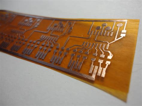
Flexible printed circuits, also known as flexible PCBs or Flex Circuits, have revolutionized the electronics industry with their versatility, durability, and compact design. Unlike traditional rigid PCBs, flexible PCBs are made using thin, flexible materials that allow them to bend, fold, and conform to various shapes and sizes. This unique characteristic has made flexible PCBs a popular choice for a wide range of applications, from consumer electronics to aerospace and medical devices.
In this comprehensive article, we will explore the different types of flexible PCBs, their benefits, and their applications across various industries. We will also discuss the manufacturing process and design considerations for flexible PCBs, as well as answer some frequently asked questions about this innovative technology.
Types of Flexible PCBs
There are several types of flexible PCBs, each with its own unique characteristics and applications. The most common types of flexible PCBs include:
1. Single-sided Flexible PCBs
Single-sided flexible PCBs have conductive traces on only one side of the flexible substrate. They are the simplest and most cost-effective type of flexible PCB, making them ideal for low-complexity applications and prototypes.
2. Double-sided Flexible PCBs
Double-sided flexible PCBs have conductive traces on both sides of the flexible substrate, allowing for higher component density and more complex designs compared to single-sided Flex PCBs. They often require through-hole vias to connect the traces on both sides.
3. Multi-layer Flexible PCBs
Multi-layer flexible PCBs consist of three or more conductive layers separated by flexible insulating layers. They offer the highest level of design complexity and component density, making them suitable for advanced applications that require a high number of interconnections and signal routing.
4. Rigid-flex PCBs
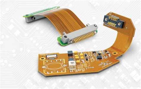
Rigid-flex PCBs combine the benefits of both rigid and flexible PCBs by incorporating rigid sections and flexible sections in a single circuit board. The rigid sections provide structural support and house components, while the flexible sections allow for bending and folding, enabling 3D packaging and reducing the overall size of the device.
Benefits of Flexible PCBs
Flexible PCBs offer numerous benefits over traditional rigid PCBs, making them an attractive choice for many applications. Some of the key benefits include:
1. Space Savings and Miniaturization
The thin, flexible nature of flex PCBs allows for a significant reduction in the overall size and weight of electronic devices. They can be folded, bent, and shaped to fit into tight spaces, enabling miniaturization and more compact designs.
2. Increased Reliability and Durability
Flexible PCBs are highly resistant to vibration, shock, and extreme temperatures, making them more reliable and durable than rigid PCBs. They can withstand repeated bending and flexing without cracking or breaking, ensuring long-term performance in demanding environments.
3. Improved Signal Integrity
The shorter interconnections and reduced component-to-component distances in flexible PCBs result in improved signal integrity and reduced electromagnetic interference (EMI). This is particularly important for high-frequency applications and sensitive electronic devices.
4. Enhanced Design Freedom
The ability to bend, fold, and conform to various shapes allows designers to create more innovative and ergonomic product designs. Flexible PCBs can be integrated seamlessly into curved surfaces, hinges, and movable parts, opening up new possibilities for product development.
5. Cost Effectiveness
Although the initial manufacturing costs of flexible PCBs may be higher than rigid PCBs, they can lead to overall cost savings by reducing the number of connectors, cables, and assembly steps required. Additionally, the increased reliability and durability of flex PCBs can result in lower maintenance and replacement costs over the product’s lifetime.

Applications of Flexible PCBs
Flexible PCBs find applications in a wide range of industries, from consumer electronics to aerospace and medical devices. Some of the most common applications include:
1. Consumer Electronics
Flexible PCBs are extensively used in consumer electronics, such as smartphones, tablets, laptops, and wearable devices. They enable slim, lightweight designs and allow for the integration of features like flexible displays and sensors.
2. Automotive Electronics
In the automotive industry, flexible PCBs are used in various applications, such as dashboard displays, infotainment systems, and sensor modules. They provide reliable performance in harsh automotive environments and enable space-saving designs.
3. Medical Devices
Flexible PCBs are a crucial component in medical devices, such as implantable devices, medical wearables, and diagnostic equipment. They offer biocompatibility, flexibility, and miniaturization, making them ideal for applications that require direct contact with the human body.
4. Aerospace and Defense
Flexible PCBs are used in aerospace and defense applications, such as avionics systems, satellite communications, and military electronics. They provide reliable performance in extreme environments, withstand vibration and shock, and enable space-saving designs.
5. Industrial Automation and Robotics
In industrial automation and robotics, flexible PCBs are used in sensors, actuators, and control systems. They offer flexibility, durability, and resistance to harsh industrial environments, enabling reliable performance in challenging conditions.
Flexible PCB Manufacturing Process
The manufacturing process for flexible PCBs is similar to that of rigid PCBs, with a few key differences to account for the flexible substrate and materials used. The general steps in the flexible PCB manufacturing process include:
-
Substrate Preparation: The flexible substrate, typically a polyimide or polyester film, is cleaned and prepared for the subsequent steps.
-
Copper Lamination: A thin layer of copper is laminated onto the flexible substrate using heat and pressure.
-
Circuit Patterning: The desired circuit pattern is transferred onto the copper layer using photolithography and etching techniques.
-
Coverlay Application: A protective coverlay is applied to the circuit pattern to insulate and protect the traces.
-
Drilling and Cutting: Holes are drilled for through-hole components, and the flexible PCB is cut to the desired shape and size.
-
Surface Finishing: The exposed copper traces are coated with a protective finish, such as gold or silver, to prevent oxidation and enhance solderability.
-
Component Assembly: Electronic components are soldered onto the flexible PCB using surface mount technology (SMT) or through-hole mounting.
-
Testing and Inspection: The assembled flexible PCB undergoes rigorous testing and inspection to ensure proper functionality and quality.
Flexible PCB Design Considerations
Designing flexible PCBs requires careful consideration of several factors to ensure optimal performance, reliability, and manufacturability. Some of the key design considerations include:
-
Material Selection: Choosing the appropriate flexible substrate and conductive materials based on the application requirements, such as temperature range, chemical resistance, and electrical properties.
-
Bend Radius: Determining the minimum bend radius for the flexible PCB to prevent damage to the traces and components during flexing.
-
Trace Width and Spacing: Designing traces with adequate width and spacing to ensure signal integrity and prevent short circuits during bending.
-
Component Placement: Positioning components strategically to minimize stress on the solder joints during flexing and to optimize the overall layout.
-
Strain Relief: Incorporating strain relief features, such as stiffeners or anchor points, to prevent excessive stress on the flexible PCB during bending.
-
Shielding and Grounding: Implementing proper shielding and grounding techniques to minimize electromagnetic interference (EMI) and ensure signal integrity.
Frequently Asked Questions (FAQ)
1. What is the typical lifespan of a flexible PCB?
The lifespan of a flexible PCB depends on various factors, such as the materials used, the application environment, and the degree of flexing. With proper design and manufacturing, flexible PCBs can last for several years or even decades in some cases.
2. Can flexible PCBs be reworked or repaired?
Yes, flexible PCBs can be reworked or repaired, but it requires specialized techniques and equipment. Rework and repair processes for flexible PCBs are more challenging compared to rigid PCBs due to the delicate nature of the flexible substrate and the need to maintain the flex
Continuing…
ibility of the circuit.
3. How do I choose the right material for my flexible PCB application?
The choice of material for a flexible PCB depends on several factors, such as the operating temperature range, chemical resistance requirements, electrical properties, and mechanical durability. Common materials used for flexible PCBs include polyimide, polyester, and thermoplastic polyurethane (TPU). Consult with a flexible PCB manufacturer or materials expert to determine the most suitable material for your specific application.
4. Can flexible PCBs be used in high-temperature environments?
Yes, certain types of flexible PCBs can be designed to withstand high-temperature environments. Polyimide-based flexible PCBs, for example, can operate in temperatures up to 200°C or higher. However, it is essential to consider the temperature ratings of all components and materials used in the flexible PCB assembly to ensure reliable performance in high-temperature conditions.
5. How do I specify the bend radius for my flexible PCB design?
The bend radius for a flexible PCB is typically specified as a multiple of the PCB thickness. A common guideline is to use a bend radius that is at least 6 times the thickness of the flexible PCB. However, the actual bend radius may vary depending on the specific materials, layer stack-up, and component placement. It is recommended to consult with your flexible PCB manufacturer and adhere to their design guidelines to ensure optimal reliability and performance.
Conclusion
Flexible PCBs have emerged as a game-changing technology in the electronics industry, offering numerous benefits such as space savings, increased reliability, improved signal integrity, and enhanced design freedom. With their ability to bend, fold, and conform to various shapes, flexible PCBs have found applications in a wide range of industries, from consumer electronics to aerospace and medical devices.
As technology continues to advance and the demand for smaller, more reliable, and more innovative electronic devices grows, the role of flexible PCBs will only become more significant. By understanding the types, benefits, and applications of flexible PCBs, as well as the key design considerations and manufacturing processes involved, engineers and product designers can leverage this innovative technology to create the next generation of cutting-edge electronic products.
At RAYPCB, we specialize in the design and manufacturing of high-quality flexible PCBs for a wide range of applications. With our state-of-the-art facilities, experienced team of engineers, and commitment to customer satisfaction, we are well-equipped to meet the evolving needs of the electronics industry. Contact us today to learn more about how our flexible PCB solutions can help bring your innovative ideas to life.
No responses yet