What are Flexible PCBs?
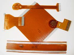
Flexible PCBs are a type of printed circuit board that consists of a thin, flexible substrate made of materials such as polyimide or polyester. These substrates are laminated with copper traces and other components, allowing for electrical connectivity while maintaining flexibility. Flex circuits can be single-sided, double-sided, or multi-layered, depending on the complexity of the design and the application requirements.
Advantages of Flexible PCBs
1. Flexibility and Durability
One of the primary advantages of flexible PCBs is their ability to bend and flex without breaking or losing their electrical properties. This flexibility allows them to be used in applications where traditional rigid PCBs would be impractical or impossible to use. Flex circuits can withstand repeated bending and twisting, making them highly durable and reliable in dynamic environments.
2. Space Savings and Weight Reduction
Flexible PCBs can be designed to fit into tight spaces and conform to irregular shapes, making them ideal for applications where space is limited. By eliminating the need for bulky connectors and wires, flex circuits can significantly reduce the overall size and weight of electronic devices. This is particularly valuable in industries such as aerospace, medical devices, and Wearable Technology, where miniaturization and weight reduction are critical.
3. Improved Signal Integrity
Flex circuits offer superior signal integrity compared to traditional wiring methods. The copper traces on a flexible PCB are printed directly onto the substrate, minimizing the distance between components and reducing the risk of signal interference. This results in cleaner, more reliable signals and faster data transmission speeds, which is essential in high-frequency applications.
4. Enhanced Thermal Management
Flexible PCBs can efficiently dissipate heat generated by electronic components, thanks to their thin profile and the use of thermally conductive materials. The ability to conform to heat sinks and other cooling solutions further enhances their thermal management capabilities. This is particularly important in applications where heat generation is a concern, such as high-power electronics and LED lighting.
5. Cost-Effective in High Volumes
While the initial setup costs for flexible PCBs may be higher than traditional rigid PCBs, they can be cost-effective in high-volume production runs. The ability to integrate multiple components and functions onto a single flex circuit can reduce the number of parts required, simplify assembly processes, and minimize labor costs. Additionally, the reduced weight and size of flex circuits can lead to cost savings in shipping and packaging.

Disadvantages of Flexible PCBs
1. Higher Initial Costs
The manufacturing process for flexible PCBs is more complex and requires specialized equipment and materials, which can result in higher initial costs compared to rigid PCBs. The design and prototyping stages may also be more time-consuming and expensive, as flex circuits often require custom layouts and extensive testing to ensure reliability and durability.
2. Limited Component Options
Due to the nature of flexible substrates, the range of components that can be used on flex circuits is somewhat limited compared to rigid PCBs. Large, heavy components or those with high heat generation may not be suitable for use on flexible PCBs. This can restrict the design options and may require additional considerations when selecting components for a flex circuit.
3. Challenging Assembly Process
Assembling components onto a flexible PCB can be more challenging than a rigid PCB, as the flexibility of the substrate can make it difficult to maintain alignment and apply consistent pressure during the soldering process. Specialized equipment and techniques, such as flexible fixturing and low-stress soldering methods, may be required to ensure reliable connections and prevent damage to the flex circuit.
4. Reduced Mechanical Strength
While flexible PCBs are highly durable in terms of their ability to withstand repeated bending and flexing, they may have reduced mechanical strength compared to rigid PCBs. The thin, flexible substrate can be more susceptible to tearing or puncturing if subjected to excessive force or sharp edges. Proper handling and protection measures must be implemented to ensure the longevity of flex circuits in demanding applications.
5. Increased Electromagnetic Interference (EMI)
The close proximity of components and traces on a flexible PCB can potentially increase the risk of electromagnetic interference (EMI). The lack of a rigid ground plane and the potential for signal traces to be closer together can make flex circuits more susceptible to EMI. Careful design considerations, such as proper grounding, shielding, and trace routing, must be implemented to mitigate EMI issues.

Manufacturing Process of Flexible PCBs
The manufacturing process of flexible PCBs involves several key steps:
-
Substrate Preparation: The flexible substrate, typically made of polyimide or polyester, is cleaned and treated to ensure proper adhesion of the copper layer.
-
Copper Lamination: A thin layer of copper is laminated onto the substrate using heat and pressure.
-
Circuit Patterning: The desired circuit pattern is transferred onto the copper layer using photolithography and etching processes.
-
Cover Layer Application: A protective cover layer, usually made of polyimide or solder mask, is applied over the circuit pattern to insulate and protect the traces.
-
Cutting and Drilling: The flex circuit is cut to the desired shape and size, and any necessary holes or vias are drilled.
-
Surface Finishing: The exposed copper areas are coated with a surface finish, such as gold or nickel, to prevent oxidation and improve solderability.
-
Assembly: Components are attached to the flex circuit using soldering or conductive adhesives, and the circuit is tested for functionality and reliability.

Applications of Flexible PCBs
Flexible PCBs find applications in a wide range of industries, including:
-
Consumer Electronics: Flex circuits are widely used in smartphones, tablets, laptops, and wearable devices, where space savings and flexibility are essential.
-
Medical Devices: Flexible PCBs are used in medical equipment such as hearing aids, pacemakers, and implantable devices, where miniaturization and reliability are critical.
-
Automotive: Flex circuits are used in various automotive applications, such as instrument clusters, sensors, and in-vehicle entertainment systems.
-
Aerospace: Flexible PCBs are used in aerospace applications, such as avionics, satellites, and missiles, where weight reduction and reliability are paramount.
-
Industrial: Flex circuits are used in industrial equipment, such as robotics, automation systems, and communication devices, where durability and flexibility are essential.
Frequently Asked Questions (FAQ)
1. What is the difference between flexible and rigid PCBs?
Flexible PCBs are made of a thin, flexible substrate that can bend and conform to various shapes, while rigid PCBs are made of a solid, non-flexible substrate. Flex circuits offer advantages such as space savings, weight reduction, and improved durability in dynamic environments, while rigid PCBs provide better mechanical strength and stability.
2. Can flexible PCBs be used for high-speed applications?
Yes, flexible PCBs can be used for high-speed applications due to their excellent signal integrity and reduced signal loss. The close proximity of components and traces on a flex circuit allows for faster signal transmission and reduced noise interference.
3. Are flexible PCBs more expensive than rigid PCBs?
The initial setup costs for flexible PCBs can be higher than rigid PCBs due to the specialized materials and manufacturing processes required. However, in high-volume production runs, flex circuits can be cost-effective due to reduced assembly time, fewer parts, and potential savings in shipping and packaging.
4. How long do flexible PCBs last?
The lifespan of a flexible PCB depends on various factors, such as the material quality, design, and operating conditions. With proper design and protection measures, flex circuits can withstand millions of bending cycles and last for several years in demanding applications.
5. Can flexible PCBs be repaired?
Repairing a flexible PCB can be challenging due to the delicate nature of the substrate and the close proximity of components. In most cases, it is more cost-effective to replace a damaged flex circuit rather than attempting to repair it. However, minor repairs, such as replacing a single component or fixing a broken trace, may be possible with specialized tools and techniques.
Conclusion
Flexible PCBs offer numerous advantages, such as flexibility, durability, space savings, weight reduction, and improved signal integrity. These benefits make them an attractive choice for a wide range of applications, from consumer electronics to medical devices and aerospace. However, flex circuits also have some disadvantages, such as higher initial costs, limited component options, and challenges in the assembly process.
When considering the use of flexible PCBs, it is essential to weigh the advantages and disadvantages based on the specific requirements of the application. Factors such as the operating environment, space constraints, and production volume should be carefully evaluated to determine if flex circuits are the most suitable choice.
As technology continues to advance, the demand for flexible PCBs is expected to grow, driven by the increasing need for miniaturization, reliability, and functionality in electronic devices. By understanding the strengths and limitations of flex circuits, designers and engineers can make informed decisions and unlock new possibilities in the ever-evolving world of electronics.
| Characteristic | Flexible PCBs | Rigid PCBs |
|---|---|---|
| Substrate Material | Polyimide, Polyester | FR-4, CEM-3, Aluminum |
| Flexibility | High | Low |
| Durability | High (withstands repeated bending) | Moderate (susceptible to cracking) |
| Space Savings | Significant | Limited |
| Weight | Low | Moderate to High |
| Signal Integrity | Excellent | Good |
| Thermal Management | Efficient (conforms to heat sinks) | Moderate (limited by substrate thickness) |
| Component Options | Limited | Extensive |
| Assembly Process | Challenging (requires specialized equipment) | Straightforward |
| Mechanical Strength | Reduced | High |
| Electromagnetic Interference (EMI) | Potentially Higher | Lower |
| Initial Costs | Higher | Lower |
| Cost-Effectiveness in High Volumes | High | Moderate |
No responses yet