Introduction to Flexible PCBs
Flexible printed circuit boards (PCBs) are a revolutionary technology that has transformed the electronics industry. Unlike traditional rigid PCBs, flexible PCBs are made from thin, pliable materials that can bend and conform to various shapes and sizes. This flexibility makes them ideal for compact devices and applications where space is limited.
Flexible PCBs have become increasingly popular in recent years due to their ability to reduce the size and weight of electronic devices while improving reliability and performance. They are used in a wide range of applications, including smartphones, wearables, medical devices, aerospace systems, and more.
Advantages of Flexible PCBs
Space Savings
One of the main advantages of flexible PCBs is their ability to save space in electronic devices. Because they can bend and fold into tight spaces, flexible PCBs allow designers to create more compact and lightweight devices. This is especially important for portable devices like smartphones and wearables, where every millimeter counts.
For example, a rigid PCB might require a larger housing to accommodate its flat shape, while a flexible PCB can be folded or wrapped around other components to minimize the overall footprint. This space savings can also lead to cost savings, as smaller devices require less materials and packaging.
Improved Reliability
Another advantage of flexible PCBs is their improved reliability compared to rigid PCBs. Because they can flex and bend without breaking, flexible PCBs are less susceptible to damage from vibrations, shocks, and other mechanical stresses. This makes them ideal for applications where durability is critical, such as aerospace systems and medical devices.
Flexible PCBs also have better thermal management than rigid PCBs. Because they can conform to the shape of other components, flexible PCBs can dissipate heat more efficiently and prevent hot spots from forming. This can help to extend the lifespan of electronic devices and prevent failures due to overheating.
Enhanced Design Freedom
Flexible PCBs offer designers greater freedom to create unique and innovative designs. Because they can be bent and shaped into various forms, flexible PCBs allow for more creative packaging and layout options. This can lead to more aesthetically pleasing and ergonomic devices that stand out in the market.
For example, a wearable device with a flexible PCB could be designed to wrap comfortably around the user’s wrist, while a medical device with a flexible PCB could be shaped to fit seamlessly into the human body. This enhanced design freedom can also enable new applications and use cases that were previously impossible with rigid PCBs.

Types of Flexible PCBs
There are several different types of flexible PCBs, each with its own unique characteristics and applications. Here are some of the most common types:
Single-Sided Flexible PCBs
Single-sided flexible PCBs have conductive traces on only one side of the substrate material. They are the simplest and most affordable type of flexible PCB, making them a popular choice for low-cost applications. Single-sided flexible PCBs are often used in keypads, membrane switches, and other simple devices.
Double-Sided Flexible PCBs
Double-sided flexible PCBs have conductive traces on both sides of the substrate material. They offer more routing options and higher component density than single-sided flexible PCBs, but are also more complex and expensive to manufacture. Double-sided flexible PCBs are commonly used in mobile phones, digital cameras, and other portable devices.
Multi-Layer Flexible PCBs
Multi-layer flexible PCBs have three or more conductive layers separated by insulating layers. They offer the highest component density and routing options of all flexible PCB types, but are also the most complex and expensive to produce. Multi-layer flexible PCBs are used in advanced applications such as aerospace systems, medical implants, and high-end consumer electronics.
Here is a table summarizing the different types of flexible PCBs:
| Type | Conductive Layers | Complexity | Cost | Common Applications |
|---|---|---|---|---|
| Single-Sided | 1 | Low | Low | Keypads, membrane switches |
| Double-Sided | 2 | Medium | Medium | Mobile phones, digital cameras |
| Multi-Layer | 3+ | High | High | Aerospace systems, medical implants |
Rigid-Flex PCBs
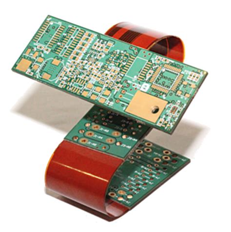
Rigid-flex PCBs are a hybrid of rigid and flexible PCBs, combining the benefits of both technologies. They consist of rigid PCB sections connected by flexible PCB sections, allowing for both stability and flexibility in the same device. Rigid-flex PCBs are often used in applications where parts of the device need to be rigid for structural support or component placement, while other parts need to be flexible for motion or space savings.
Rigid-flex PCBs offer several advantages over traditional rigid or flexible PCBs alone. They can reduce the need for connectors and cables between rigid sections, improving reliability and signal integrity. They also allow for more complex 3D packaging and assembly options, as the flexible sections can be folded or twisted into various shapes.
However, rigid-flex PCBs are also more complex and expensive to design and manufacture than single-type PCBs. They require careful planning and layout to ensure proper flexing and assembly, and may need specialized materials and processes for fabrication.

Materials Used in Flexible PCBs
Flexible PCBs are made from a variety of materials that provide the necessary flexibility, durability, and electrical properties. Here are some of the most common materials used in flexible PCBs:
Polyimide (PI)
Polyimide (PI) is the most widely used substrate material for flexible PCBs. It is a high-performance polymer that offers excellent thermal stability, chemical resistance, and mechanical strength. PI has a high glass transition temperature (Tg) of around 360°C, allowing it to withstand the high temperatures used in PCB manufacturing processes.
PI is available in various grades and thicknesses to suit different applications. The most common type of PI used in flexible PCBs is Kapton, which is a trademarked brand of PI film developed by DuPont. Kapton is known for its high dielectric strength, low moisture absorption, and resistance to solvents and acids.
Polyethylene Terephthalate (PET)
Polyethylene terephthalate (PET) is another common substrate material for flexible PCBs. It is a thermoplastic polymer that offers good flexibility, transparency, and electrical insulation properties. PET is often used in applications where cost is a primary concern, as it is less expensive than PI.
However, PET has a lower Tg of around 80°C, which limits its use in high-temperature applications. It also has lower chemical resistance and dimensional stability than PI, which can affect the reliability of the PCB over time.
Copper
Copper is the most common conductive material used in flexible PCBs. It is used to create the conductive traces and pads that carry electrical signals between components. Copper is chosen for its high electrical conductivity, thermal conductivity, and ductility, which allows it to bend and flex without breaking.
The thickness of the copper layer in a flexible PCB can vary depending on the application and design requirements. Thinner copper layers are more flexible but have higher resistance, while thicker copper layers are less flexible but can carry more current.
Adhesives
Adhesives are used in flexible PCBs to bond the conductive layers to the substrate material and to provide insulation between layers. The most common type of adhesive used in flexible PCBs is acrylic, which offers good flexibility, adhesion, and chemical resistance.
Other types of adhesives used in flexible PCBs include epoxy, silicone, and pressure-sensitive adhesives (PSAs). The choice of adhesive depends on the specific application requirements, such as temperature range, chemical exposure, and flexibility needs.
Here is a table comparing the properties of some common flexible PCB materials:
| Material | Dielectric Constant | Dielectric Strength (kV/mm) | Tensile Strength (MPa) | Tg (°C) |
|---|---|---|---|---|
| PI (Kapton) | 3.5 | 300 | 231 | 360 |
| PET | 3.2 | 20 | 150 | 80 |
| Acrylic Adhesive | 3.5 | 20 | 25 | -45 to 120 |

Designing Flexible PCBs
Designing flexible PCBs requires a different approach than designing rigid PCBs. Flexible PCBs have unique mechanical and electrical requirements that must be considered during the design process. Here are some key considerations for designing flexible PCBs:
Bend Radius
The bend radius is the minimum radius that a flexible PCB can be bent without damaging the conductive traces or substrate material. The bend radius depends on the thickness and material of the PCB, as well as the location and orientation of the components.
In general, the minimum bend radius should be at least 6 times the thickness of the PCB. For example, a 0.2mm thick flexible PCB should have a minimum bend radius of 1.2mm. However, this is just a general guideline, and the actual bend radius may need to be larger or smaller depending on the specific design requirements.
Flexible Zones
Flexible zones are areas of the PCB that are designed to flex and bend during use. These zones should be free of components and have a uniform copper pattern to prevent stress concentrations. The copper traces in flexible zones should also be routed in a serpentine pattern to allow for stretching and bending without breaking.
Flexible zones should be separated from rigid zones by a buffer area that allows for a smooth transition between the two. This buffer area should have a gradual change in copper density and trace width to prevent sudden changes in flexibility.
Component Placement
Component placement is critical in flexible PCB design. Components should be placed in rigid zones whenever possible to prevent damage from flexing and bending. If components must be placed in flexible zones, they should be small, lightweight, and have flexible terminations such as ribbon cables or stretchable interconnects.
Components should also be placed as close to the neutral axis of the PCB as possible to minimize stress during bending. The neutral axis is the plane where the compressive and tensile stresses cancel out, resulting in zero stress.
Stiffeners
Stiffeners are rigid materials that are added to flexible PCBs to provide structural support and prevent excessive bending. They are typically made from metal, plastic, or fiberglass and are bonded to the PCB using adhesives.
Stiffeners can be used to create rigid zones in flexible PCBs, such as connector areas or component mounting zones. They can also be used to reinforce flexible zones and prevent damage from overstressing.
Coverlay
Coverlay is a protective layer that is added to the surface of flexible PCBs to provide insulation and mechanical protection. It is typically made from PI or PET and is bonded to the PCB using adhesives.
Coverlay can be used to encapsulate components, protect exposed copper traces, and provide a smooth surface for printing or labeling. It can also be used to create stiffened areas or flexible hinges in the PCB.
Manufacturing Flexible PCBs
Manufacturing flexible PCBs involves several specialized processes that are different from rigid PCB manufacturing. Here are some of the key steps in flexible PCB manufacturing:
Substrate Preparation
The first step in flexible PCB manufacturing is to prepare the substrate material. This involves cutting the PI or PET film to the desired size and shape, and cleaning it to remove any contaminants or debris.
The substrate material is then coated with a layer of copper foil using an adhesive. The copper foil is typically 18-35 microns thick and is bonded to the substrate using heat and pressure.
Circuit Patterning
Once the copper-clad substrate is prepared, the circuit pattern is transferred onto the copper layer using a photolithography process. This involves coating the copper with a light-sensitive resist, exposing it to UV light through a photomask, and developing the resist to remove the unexposed areas.
The exposed copper is then etched away using a chemical or plasma etching process, leaving behind the desired circuit pattern. The remaining resist is then stripped away, leaving the bare copper traces.
Lamination
After the circuit pattern is etched, additional layers of PI or PET film are laminated onto the substrate using adhesives. These layers provide insulation between the conductive layers and protect the circuits from damage.
The lamination process involves aligning the layers and pressing them together under heat and pressure to bond them into a single, unified structure. The temperature and pressure used in the lamination process must be carefully controlled to prevent delamination or damage to the circuits.
Drilling and Cutting
Once the laminated structure is complete, holes are drilled through the PCB to create vias and mounting holes. The vias are then plated with copper to provide electrical connections between layers.
The PCB is then cut to its final shape and size using a laser or mechanical cutting process. The edges of the PCB may be sealed or coated to prevent delamination or moisture ingress.
Surface Finishing
The final step in flexible PCB manufacturing is to apply a surface finish to the exposed copper traces. This finish provides protection against oxidation and corrosion, and improves the solderability of the pads.
Common surface finishes for flexible PCBs include:
- ENIG (Electroless Nickel Immersion Gold)
- OSP (Organic Solderability Preservative)
- Immersion Silver
- Immersion Tin
The choice of surface finish depends on the specific application requirements, such as operating environment, storage conditions, and soldering process.
Applications of Flexible PCBs
Flexible PCBs are used in a wide range of applications where flexibility, space savings, and reliability are critical. Here are some of the most common applications of flexible PCBs:
Consumer Electronics
Flexible PCBs are widely used in consumer electronics, such as smartphones, tablets, and wearables. They allow for more compact and lightweight designs, as well as improved durability and reliability.
For example, a smartwatch with a flexible PCB can be designed to wrap comfortably around the user’s wrist, while still providing all the necessary functionality and features. The flexible PCB can also be folded or twisted to fit into the small space inside the watch case, without sacrificing performance or reliability.
Medical Devices
Flexible PCBs are also used in medical devices, such as pacemakers, hearing aids, and implantable sensors. They allow for smaller and more comfortable devices that can be worn or implanted in the body for long periods of time.
For example, a pacemaker with a flexible PCB can be designed to fit comfortably inside the chest cavity, while still providing reliable and accurate monitoring and stimulation of the heart. The flexible PCB can also be shaped to conform to the curvature of the body, reducing the risk of tissue damage or infection.
Automotive Electronics
Flexible PCBs are increasingly being used in automotive electronics, such as infotainment systems, dashboard displays, and sensor modules. They offer improved reliability and space savings compared to traditional rigid PCBs, as well as the ability to conform to complex shapes and contours.
For example, a flexible PCB can be used to create a curved dashboard display that seamlessly integrates with the interior design of the vehicle. The flexible PCB can also be used to connect sensors and modules located in different parts of the vehicle, without the need for bulky cables or connectors.
Aerospace and Defense
Flexible PCBs are used in aerospace and defense applications, where reliability and performance are critical. They offer improved resistance to vibration, shock, and extreme temperatures, as well as the ability to conform to complex shapes and structures.
For example, a flexible PCB can be used to create a compact and lightweight avionics module that can withstand the harsh conditions of space flight. The flexible PCB can also be used to connect sensors and actuators located in different parts of the aircraft or spacecraft, without adding significant weight or complexity.
Industrial Equipment
Flexible PCBs are used in industrial equipment, such as robotics, automation systems, and control panels. They offer improved flexibility and durability compared to rigid PCBs, as well as the ability to fit into tight spaces and conform to moving parts.
For example, a flexible PCB can be used to create a compact and lightweight robotic arm that can move and flex without breaking or losing connectivity. The flexible PCB can also be used to connect sensors and actuators located in different parts of the machine, without the need for complex wiring or harnessing.
Advantages of Flexible PCBs
Flexible PCBs offer several advantages over traditional rigid PCBs, including:
- Space savings: Flexible PCBs can be folded, bent, or rolled to fit into tight spaces, allowing for more compact and lightweight designs.
- Improved reliability: Flexible PCBs are more resistant to vibration, shock, and thermal stress than rigid PCBs, improving overall system reliability.
- Enhanced design freedom: Flexible PCBs can be shaped and contoured to fit complex geometries and structures, allowing for more creative and innovative designs.
- Reduced assembly costs: Flexible PCBs can reduce the need for connectors, cables, and other interconnects, simplifying assembly and reducing costs.
- Better signal integrity: Flexible PCBs can provide shorter and more direct signal paths than rigid PCBs, reducing noise, crosstalk, and signal loss.
Challenges of Flexible PCBs
Despite their many advantages, flexible PCBs also present some challenges and limitations, including:
- Higher design complexity: Flexible PCBs require careful consideration of mechanical and electrical properties, as well as specialized design rules and guidelines.
- Limited component options: Flexible PCBs may not be able to accommodate large or heavy components, or
No responses yet