Introduction to Flex Sensors
Flex sensors, also known as bend sensors, are resistive sensors that change their resistance when bent or flexed. They are commonly used in various applications, such as wearable devices, robotics, and gaming controllers, to measure the degree of bending or flexing. In this article, we will explore the working principle of flex sensors and how to interface them with an Arduino microcontroller.
What is a Flex Sensor?
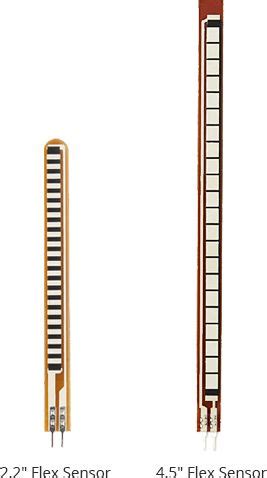
A flex sensor is a thin, flexible strip that contains a layer of conductive material, typically carbon or polymer ink, printed on a flexible substrate. As the sensor is bent, the conductive layer experiences stress, causing micro-cracks to form. These micro-cracks result in a change in the sensor’s resistance, which can be measured and used to determine the degree of bending.
Flex sensors are available in various sizes and resistance ranges. The most common sizes are 2.2 inches and 4.5 inches, with resistance ranges from 10kΩ to 50kΩ in the flat position and up to 100kΩ or more when bent to 90 degrees.
Flex Sensor Characteristics
Flex sensors have several key characteristics that make them suitable for various applications:
- Resistance change: The resistance of a flex sensor increases as it is bent, allowing for the measurement of the degree of bending.
- Durability: Flex sensors are designed to withstand repeated bending cycles without significant degradation in performance.
- Simple interface: Flex sensors can be easily interfaced with microcontrollers, such as Arduino, using a simple voltage divider circuit.
- Low power consumption: Flex sensors consume minimal power, making them suitable for battery-powered applications.
The Working Principle of Flex Sensors
Piezoresistive Effect
The working principle of flex sensors is based on the piezoresistive effect, which is the change in the electrical resistance of a material when subjected to mechanical stress. In the case of flex sensors, the conductive layer experiences stress when the sensor is bent, causing micro-cracks to form and increasing the resistance.
Resistance Change vs. Bending Angle
The relationship between the resistance change and the bending angle of a flex sensor is not linear. As the bending angle increases, the resistance change becomes more pronounced. The exact relationship depends on factors such as the sensor’s size, material composition, and manufacturing process.
To accurately measure the bending angle using a flex sensor, it is necessary to calibrate the sensor and create a lookup table or a mathematical model that relates the resistance change to the bending angle.
Voltage Divider Circuit
To measure the resistance change of a flex sensor, a voltage divider circuit is commonly used. In this circuit, the flex sensor is connected in series with a fixed resistor, forming a voltage divider. The output voltage of the voltage divider is proportional to the resistance of the flex sensor and can be measured using an analog input pin of a microcontroller, such as an Arduino.
The voltage divider circuit can be represented by the following equation:
Vout = Vin * (Rflex / (Rflex + Rfixed))
Where:
– Vout is the output voltage of the voltage divider
– Vin is the input voltage (typically the microcontroller’s supply voltage)
– Rflex is the resistance of the flex sensor
– Rfixed is the resistance of the fixed resistor
By measuring the output voltage and knowing the input voltage and fixed resistor value, the resistance of the flex sensor can be calculated using the following equation:
Rflex = Rfixed * ((Vin / Vout) - 1)

Interfacing Flex Sensor with Arduino
Hardware Requirements
To interface a flex sensor with an Arduino, you will need the following components:
- Arduino board (e.g., Arduino Uno)
- Flex sensor
- 10kΩ resistor
- Breadboard
- Jumper wires
Circuit Diagram
The circuit diagram for interfacing a flex sensor with an Arduino is shown below:
Flex Sensor
   │
   ├─────────────────┬──────────────────────────┐
   │                 │                          │
   │              10kΩ Resistor               Arduino
   │                 │                          │
   │                 ├──────────────────────────┤
   │                 │                          │
   └─────────────────┴───────────────────── GND │
                                                │
                                            Analog Pin
In this circuit, the flex sensor is connected in series with the 10kΩ resistor, forming a voltage divider. The output of the voltage divider is connected to an analog input pin of the Arduino (e.g., A0). The other end of the flex sensor is connected to the Arduino’s ground (GND).
Arduino Code
Here’s an example Arduino code for reading the flex sensor value and converting it to a bending angle:
const int flexPin = A0;  // Analog input pin for the flex sensor
const float VCC = 5.0;   // Arduino supply voltage
const float R_DIV = 10000.0;  // Fixed resistor value (10kΩ)

void setup() {
  Serial.begin(9600);  // Initialize serial communication
}

void loop() {
  int flexValue = analogRead(flexPin);  // Read the analog value from the flex sensor
  float flexVoltage = flexValue * VCC / 1023.0;  // Convert the analog value to voltage
  float flexResistance = R_DIV * (VCC / flexVoltage - 1.0);  // Calculate the resistance of the flex sensor
  float bendAngle = map(flexResistance, 10000, 50000, 0, 90);  // Convert resistance to bend angle (0-90 degrees)

  Serial.print("Bend Angle: ");
  Serial.print(bendAngle);
  Serial.println(" degrees");

  delay(500);  // Wait for 500ms before the next reading
}
This code does the following:
- It defines constants for the analog input pin (
flexPin), Arduino supply voltage (VCC), and the fixed resistor value (R_DIV). - In the
setup()function, it initializes serial communication at a baud rate of 9600. - In the
loop()function, it reads the analog value from the flex sensor usinganalogRead(). - It converts the analog value to voltage using the equation:
flexVoltage = flexValue * VCC / 1023.0. - It calculates the resistance of the flex sensor using the voltage divider equation:
flexResistance = R_DIV * (VCC / flexVoltage - 1.0). - It maps the resistance value to a bend angle (0-90 degrees) using the
map()function. The resistance range (10000-50000) and the corresponding angle range (0-90) are based on the characteristics of the specific flex sensor used. - It prints the bend angle to the serial monitor.
- It waits for 500ms before taking the next reading.
Calibration and Mapping
The resistance range and the corresponding bend angle range used in the Arduino code example are based on typical values for a standard flex sensor. However, these values may vary depending on the specific sensor and its characteristics.
To ensure accurate measurements, it is recommended to calibrate the flex sensor and determine the appropriate resistance range and bend angle range for your specific sensor. This can be done by measuring the sensor’s resistance at different known bend angles and creating a lookup table or a mathematical model that relates the resistance to the bend angle.
Once the calibration is complete, the map() function in the Arduino code can be adjusted to use the appropriate resistance and bend angle ranges for your sensor.

Applications of Flex Sensors
Flex sensors find applications in various fields, including:
- Wearable devices: Flex sensors can be integrated into gloves, clothing, or other wearable items to track hand gestures, body movements, or posture.
- Robotics: Flex sensors can be used in robotic grippers or joints to provide feedback on the degree of bending or flexing, enabling precise control and manipulation.
- Gaming controllers: Flex sensors can be incorporated into gaming controllers to detect finger or hand movements, enhancing the gaming experience.
- Virtual reality (VR) and augmented reality (AR): Flex sensors can be used in VR and AR systems to track hand and finger movements, enabling more immersive and interactive experiences.
- Medical devices: Flex sensors can be used in medical devices, such as rehabilitation equipment or prosthetics, to monitor and track patient movements and progress.

Advantages and Limitations of Flex Sensors
Advantages
- Simple and easy to use: Flex sensors are simple to interface with microcontrollers and require minimal additional components.
- Lightweight and flexible: Flex sensors are thin, lightweight, and flexible, making them suitable for integration into various devices and applications.
- Low power consumption: Flex sensors consume minimal power, making them ideal for battery-powered devices.
- Durable: Flex sensors are designed to withstand repeated bending cycles without significant degradation in performance.
Limitations
- Non-linear response: The relationship between the resistance change and the bending angle of a flex sensor is not linear, requiring calibration and mapping for accurate measurements.
- Hysteresis: Flex sensors may exhibit hysteresis, meaning that the resistance value may not return to its original value after bending, leading to measurement inaccuracies.
- Temperature sensitivity: The resistance of flex sensors can be affected by changes in temperature, which may require compensation techniques for accurate measurements in varying temperature conditions.
- Limited bending range: Flex sensors have a limited bending range, typically up to 90 degrees, which may not be sufficient for certain applications requiring a wider range of motion.
Conclusion
Flex sensors are versatile and easy-to-use components that enable the measurement of bending or flexing in various applications. By understanding the working principle of flex sensors and how to interface them with microcontrollers like Arduino, designers and engineers can create innovative projects that respond to bending and movement.
When using flex sensors, it is important to consider factors such as calibration, mapping, and the specific characteristics of the sensor to ensure accurate and reliable measurements. With their simple interface, low power consumption, and durability, flex sensors offer a compelling solution for applications ranging from wearable devices to robotics and beyond.
FAQ
-
What is the typical resistance range of a flex sensor?
The typical resistance range of a flex sensor is 10kΩ to 50kΩ in the flat position and up to 100kΩ or more when bent to 90 degrees. However, the exact resistance range may vary depending on the specific sensor and its characteristics. -
How do I calibrate a flex sensor?
To calibrate a flex sensor, you need to measure its resistance at different known bend angles and create a lookup table or a mathematical model that relates the resistance to the bend angle. This can be done by using a protractor or a goniometer to measure the bend angles and recording the corresponding resistance values. -
Can I use a flex sensor for measuring angles greater than 90 degrees?
Most flex sensors have a limited bending range, typically up to 90 degrees. If you need to measure angles greater than 90 degrees, you may need to consider using multiple flex sensors or alternative sensing technologies, such as potentiometers or rotary encoders. -
How can I compensate for temperature variations when using a flex sensor?
To compensate for temperature variations, you can use a temperature sensor alongside the flex sensor and measure the ambient temperature. Then, you can apply a temperature compensation algorithm to adjust the flex sensor readings based on the temperature changes. This can be done in software by implementing a temperature compensation formula or lookup table. -
Can I use a flex sensor for long-term continuous monitoring applications?
Flex sensors are designed to withstand repeated bending cycles and are suitable for long-term use. However, over time, the sensor’s performance may degrade due to fatigue or wear. It is important to consider the expected lifetime of the sensor and the specific requirements of your application when choosing a flex sensor for long-term continuous monitoring.
| Component | Quantity |
|---|---|
| Arduino board | 1 |
| Flex sensor | 1 |
| 10kΩ resistor | 1 |
| Breadboard | 1 |
| Jumper wires | As needed |
| Bend Angle (degrees) | Resistance (kΩ) |
|---|---|
| 0 | 10 |
| 30 | 20 |
| 60 | 35 |
| 90 | 50 |
The above tables provide a list of the required components for interfacing a flex sensor with an Arduino and an example lookup table for mapping resistance values to bend angles based on calibration data.
No responses yet