Introduction to ExpressPCB
ExpressPCB is a PCB design software that allows users to create professional-quality PCBs quickly and easily. It offers a wide range of features and tools, making it suitable for both hobbyists and professionals. With ExpressPCB, you can design single or double-sided PCBs, create schematic diagrams, and generate Gerber files for manufacturing.
Key Features of ExpressPCB
- User-friendly interface
- Schematic capture and PCB layout design
- Extensive component libraries
- Automatic routing and manual routing options
- Design rule checking (DRC) for error-free designs
- Gerber File Generation for manufacturing
Getting Started with ExpressPCB
Before diving into the PCB design process, let’s set up the software and familiarize ourselves with the user interface.
System Requirements
To run ExpressPCB, your computer should meet the following minimum requirements:
- Operating System: Windows 7, 8, 10, or 11
- Processor: 1 GHz or faster
- RAM: 2 GB or more
- Disk Space: 500 MB free space
Installing ExpressPCB
- Visit the official ExpressPCB website (https://www.expresspcb.com/) and download the latest version of the software.
- Run the installer and follow the on-screen instructions to complete the installation process.
- Launch ExpressPCB from the desktop shortcut or the Start menu.
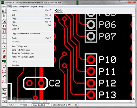
User Interface Overview
Upon launching ExpressPCB, you will be greeted with the main window, which consists of several key areas:
- Menu Bar: Located at the top of the window, the menu bar provides access to various functions and settings.
- Toolbar: Below the menu bar, the toolbar contains icons for frequently used tools and commands.
- Workspace: The central area of the window where you design your schematic and PCB layouts.
- Component Libraries: On the left side of the window, you will find the component libraries, which contain a wide range of electronic components.
- Properties Panel: On the right side of the window, the properties panel displays the properties of the selected object, allowing you to modify its settings.

Designing a Schematic in ExpressPCB
The first step in creating a PCB is to design the schematic diagram, which represents the electrical connections between components.
Creating a New Schematic
- Go to “File” > “New” > “Schematic” to create a new schematic document.
- Set the sheet size and orientation according to your project requirements.
- Save the schematic file with a descriptive name.
Adding Components
- Locate the desired component in the component libraries on the left side of the window.
- Drag and drop the component onto the schematic workspace.
- Repeat the process for all the components needed in your circuit.
Connecting Components
- Select the “Wire” tool from the toolbar.
- Click on the first component’s pin and drag the wire to the second component’s pin to create a connection.
- Continue connecting all the necessary components according to your circuit diagram.
Labeling Components and Nets
- Select the “Text” tool from the toolbar.
- Click on the schematic workspace where you want to add a label.
- Type the desired label text and adjust its properties (size, font, etc.) in the properties panel.
- Repeat the process for all the components and nets that require labeling.

PCB Layout Design in ExpressPCB
Once you have completed the schematic design, it’s time to create the PCB layout, which determines the physical arrangement of components and traces on the board.
Creating a New PCB Layout
- Go to “File” > “New” > “PCB” to create a new PCB layout document.
- Set the board size, layer stack-up, and other parameters according to your project requirements.
- Save the PCB layout file with a descriptive name.
Placing Components
- Go to “Tools” > “Update PCB with Schematic” to import the components from the schematic to the PCB layout.
- Arrange the components on the board by dragging and dropping them to the desired locations.
- Consider factors such as component size, orientation, and spacing when placing components.
Routing Traces
- Select the “Route” tool from the toolbar.
- Click on a component pin to start a trace and click on the destination pin to complete the trace.
- Adjust the trace width and spacing in the properties panel to meet your design requirements.
- Continue routing all the necessary traces, ensuring that they do not overlap or violate any design rules.
Applying Design Rules
- Go to “Tools” > “Design Rules” to open the design rule settings.
- Set the appropriate design rules, such as minimum trace width, clearance, and hole size, based on your manufacturing specifications.
- Run the design rule check (DRC) by going to “Tools” > “DRC” to identify and fix any rule violations.
Generating Gerber Files
- Go to “File” > “Export” > “Gerber Files” to open the Gerber file generation dialog.
- Select the desired layers to export and specify the output directory.
- Click “Export” to generate the Gerber files, which can be sent to a PCB manufacturer for production.

Advanced Features and Tips
Using the Autorouter
ExpressPCB includes an autorouter that can automatically route traces on your PCB layout. To use the autorouter:
- Go to “Tools” > “Autorouter” to open the autorouter settings.
- Configure the autorouter parameters, such as trace width, via spacing, and routing strategy.
- Click “Route” to start the autorouting process.
- Review the autorouted traces and make manual adjustments if necessary.
Creating Custom Components
If your design requires components that are not available in the built-in libraries, you can create custom components in ExpressPCB:
- Go to “File” > “New” > “Component” to create a new component.
- Draw the component symbol using the available drawing tools.
- Define the component properties, such as pin names and types, in the properties panel.
- Save the custom component and add it to your schematic and PCB layouts as needed.
Collaborating with Others
ExpressPCB allows you to collaborate with team members and share your designs easily:
- Go to “File” > “Export” > “ExpressPCB Files” to export your schematic and PCB layout files.
- Share the exported files with your team members via email, cloud storage, or version control systems.
- Your team members can import the files into their ExpressPCB software and make changes or additions to the design.
Frequently Asked Questions (FAQ)
-
Can I create multi-layer PCBs with ExpressPCB?
Yes, ExpressPCB supports the design of multi-layer PCBs. You can specify the number of layers and the layer stack-up in the PCB layout settings. -
Is ExpressPCB suitable for beginners?
Yes, ExpressPCB is designed to be user-friendly and intuitive, making it a great choice for beginners. The software provides a simple interface and includes helpful tutorials and resources to guide you through the PCB design process. -
Can I import and export designs from other PCB software?
ExpressPCB supports the import and export of various file formats, including Gerber files, Excellon drill files, and IPC-D-356 netlist files. This allows you to collaborate with others who may be using different PCB design software. -
Does ExpressPCB offer simulation capabilities?
No, ExpressPCB is primarily a PCB design software and does not include built-in simulation capabilities. For Circuit Simulation, you may need to use separate software such as SPICE or Multisim. -
How can I obtain technical support for ExpressPCB?
ExpressPCB provides technical support through their website and user forums. You can visit the ExpressPCB support page (https://www.expresspcb.com/support/) to access FAQs, tutorials, and user forums where you can ask questions and seek assistance from the ExpressPCB community.
Conclusion
Congratulations! You have now learned the basics of using ExpressPCB to design and create your own PCBs. By following this step-by-step tutorial, you should be able to navigate the software, design schematics, create PCB layouts, and generate manufacturing files.
Remember to practice and experiment with the various features and tools offered by ExpressPCB to further enhance your PCB design skills. Don’t hesitate to refer to the official documentation, tutorials, and user forums for additional guidance and inspiration.
With ExpressPCB, you have the power to bring your electronic projects to life. Happy PCB designing!
No responses yet