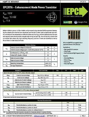
Introduction to Datasheets
Datasheets are essential documents that provide critical information about electronic components, including their specifications, features, and performance characteristics. They serve as a primary reference for engineers, designers, and technicians when selecting components for their projects or troubleshooting issues. In this article, we will explore the importance of datasheets and how they impact your design process, with a focus on dk (dielectric constant) and its relevance in electronic design.
What is a Datasheet?
A datasheet is a document that contains detailed technical information about an electronic component, such as a resistor, capacitor, integrated circuit, or semiconductor. It is typically provided by the manufacturer and includes data on the component’s electrical, mechanical, and thermal properties, as well as its recommended operating conditions and limitations.
Datasheets are crucial for engineers and designers as they help them make informed decisions when selecting components for their projects. They provide a wealth of information that can be used to optimize designs, improve performance, and ensure reliability.
Key Information Found in Datasheets
Datasheets contain a wide range of information that is essential for designers and engineers. Some of the key information found in datasheets includes:
-
Electrical Characteristics: This includes data on the component’s voltage and current ratings, power dissipation, and other electrical properties.
-
Mechanical Characteristics: This includes information on the component’s dimensions, weight, and packaging.
-
Thermal Characteristics: This includes data on the component’s operating temperature range and thermal resistance.
-
Performance Characteristics: This includes information on the component’s frequency response, noise, and other performance metrics.
-
Application Notes: This includes recommendations on how to use the component in different applications and circuits.
Understanding dk (Dielectric Constant)
One of the key parameters found in datasheets for certain components, such as capacitors and printed circuit board (PCB) materials, is the dielectric constant (dk). Understanding dk is crucial for designing high-frequency circuits and optimizing the performance of your electronic devices.
What is dk?
The dielectric constant, also known as the relative permittivity, is a measure of a material’s ability to store electric charge. It is a dimensionless quantity that describes how much a material concentrates electric flux compared to vacuum.
In simpler terms, dk represents the ratio of the capacitance of a capacitor filled with a given material to the capacitance of the same capacitor in a vacuum. A higher dk value indicates that the material has a greater ability to store electric charge.
Importance of dk in Electronic Design
The dielectric constant plays a crucial role in various aspects of electronic design, particularly in high-frequency applications. Some of the key areas where dk is important include:
-
Capacitor Selection: The dk value of a capacitor’s dielectric material determines its capacitance and performance characteristics. Higher dk materials allow for smaller capacitor sizes but may have lower voltage ratings and higher leakage currents.
-
PCB Material Selection: The dk of a PCB material affects the propagation velocity and impedance of signals traveling through the board. Lower dk materials generally have lower signal loss and are preferred for high-frequency designs.
-
Impedance Matching: Matching the impedance of components and transmission lines is essential for minimizing signal reflections and ensuring optimal power transfer. The dk of the materials used in the design influences the characteristic impedance of the system.
-
Signal Integrity: The dk of materials used in a design can impact signal integrity by affecting the propagation delay, rise time, and other characteristics of signals traveling through the system.
Common dk Values for Electronic Materials
Here are some common dk values for materials frequently used in electronic design:
| Material | dk (at 1 MHz) |
|---|---|
| Air | 1.0006 |
| Teflon (PTFE) | 2.1 |
| Polyethylene (PE) | 2.25 |
| FR-4 (PCB Material) | 4.5 |
| Alumina (Al2O3) | 9.9 |
| Barium Titanate (BaTiO3) | 1000-5000 |
It’s important to note that dk values can vary with frequency and temperature, so designers should consult the relevant datasheets for accurate information specific to their application.

Impact of Datasheets on Your Design Process
Datasheets play a vital role in every stage of the electronic design process, from concept development to final production. Let’s explore how datasheets impact your design process and why they are essential for creating successful electronic products.
Component Selection
One of the primary uses of datasheets is for component selection. When designing an electronic circuit, engineers must choose components that meet the specific requirements of their application, such as voltage and current ratings, power dissipation, and performance characteristics.
Datasheets provide the necessary information to compare different components and select the most suitable one for the design. By carefully reviewing the datasheet specifications, designers can ensure that the chosen components will perform as expected and meet the design requirements.
Circuit Design and Simulation
Datasheets are also crucial for circuit design and simulation. When creating a new electronic circuit, designers often use simulation software to model the behavior of the circuit and optimize its performance. To accurately simulate the circuit, designers need to input the component parameters from the datasheets into the simulation software.
Using the information provided in the datasheets, designers can create more accurate models of their circuits and predict their performance under different operating conditions. This helps identify potential issues early in the design process and allows for optimization before physical prototyping.
PCB Layout and Manufacturing
Datasheets play a significant role in PCB layout and manufacturing. When designing a PCB, engineers must consider factors such as component footprints, pad sizes, and spacing requirements. Datasheets provide the necessary mechanical information, such as component dimensions and recommended PCB land patterns, to ensure proper component placement and soldering.
Additionally, datasheets often include information on the thermal characteristics of components, such as thermal resistance and maximum operating temperature. This information is essential for designing appropriate cooling solutions and ensuring that components operate within their specified temperature ranges.
Testing and Debugging
Datasheets are indispensable for testing and debugging electronic circuits. When troubleshooting a circuit, engineers often refer to the datasheets to understand the expected behavior of components and identify potential issues.
Datasheets provide information on the typical performance characteristics of components, such as input/output voltages, current consumption, and timing parameters. By comparing the actual measured values to the datasheet specifications, engineers can pinpoint problems and develop solutions more effectively.
Compliance and Certification
Finally, datasheets are essential for ensuring compliance with industry standards and obtaining necessary certifications. Many electronic products must meet specific safety, electromagnetic compatibility (EMC), and environmental requirements before they can be sold in certain markets.
Datasheets provide information on the compliance of components with relevant standards, such as RoHS (Restriction of Hazardous Substances) and REACH (Registration, Evaluation, Authorization, and Restriction of Chemicals). This information helps designers select components that meet the required standards and simplifies the compliance and certification process for the final product.

Best Practices for Using Datasheets
To make the most of datasheets and ensure the success of your electronic design projects, follow these best practices:
-
Always use the latest version of the datasheet: Manufacturers often update datasheets to include new information or correct errors. Ensure that you are using the most recent version of the datasheet to avoid potential issues.
-
Read the entire datasheet: Don’t just focus on the key specifications; read the entire datasheet to understand the component’s features, limitations, and recommended usage conditions.
-
Pay attention to the test conditions: Datasheet specifications are typically provided for specific test conditions, such as temperature, frequency, and bias voltage. Make sure to consider these conditions when using the data in your design.
-
Understand the terminology: Datasheets often use technical terms and abbreviations that may be unfamiliar to some designers. Take the time to understand the terminology used in the datasheet to avoid misinterpretation.
-
Verify the component’s availability and lead time: Before finalizing your design, check the availability and lead time of the selected components. Some components may have long lead times or may be discontinued, which could impact your project timeline.
-
Consider the environmental conditions: Datasheets provide information on the component’s operating temperature range, humidity tolerance, and other environmental factors. Ensure that your design can withstand the expected environmental conditions.
-
Use reliable sources: Obtain datasheets from reputable sources, such as the manufacturer’s official website or authorized distributors, to ensure the accuracy and reliability of the information.

Frequently Asked Questions (FAQ)
-
What should I do if I can’t find the datasheet for a component?
If you cannot find the datasheet for a specific component, try contacting the manufacturer directly or searching for the component on distributor websites. In some cases, you may find datasheets for similar components that can provide useful information. -
Can I use a component beyond its datasheet specifications?
Using a component beyond its specified ratings can lead to reduced performance, reliability issues, or even permanent damage. It is generally not recommended to use components outside their datasheet specifications unless you have a thorough understanding of the potential risks and have conducted appropriate testing. -
How do I interpret the graphs and charts in a datasheet?
Datasheets often include graphs and charts to display the component’s performance characteristics under different conditions. To interpret these graphs, pay attention to the axes labels, units, and any notes or captions that provide additional information. If you are unsure about how to interpret a specific graph, consult the datasheet’s application notes or contact the manufacturer for clarification. -
What if there is a discrepancy between the datasheet and my design simulation results?
If you observe a discrepancy between the datasheet specifications and your design simulation results, first double-check that you have entered the correct component parameters in your simulation software. If the discrepancy persists, consult the datasheet’s application notes or contact the manufacturer’s technical support for guidance. In some cases, the discrepancy may be due to limitations in the simulation model or differences in test conditions. -
How do I select the right component when there are multiple options with similar specifications?
When faced with multiple components that meet your design requirements, consider factors such as cost, availability, reliability, and the manufacturer’s reputation. Look for components with a proven track record in similar applications and consult with experienced designers or industry forums for recommendations. In some cases, conducting real-world testing with different components can help you make an informed decision.
Conclusion
Datasheets are indispensable tools for electronic design, providing critical information that helps engineers and designers make informed decisions throughout the development process. By understanding the importance of dk and other key parameters found in datasheets, designers can optimize their circuits for performance, reliability, and compliance with industry standards.
To leverage the full potential of datasheets, designers should follow best practices such as using the latest version of the datasheet, reading the entire document, and paying attention to test conditions and terminology. By doing so, they can avoid common pitfalls and ensure the success of their electronic design projects.
As technology continues to advance and electronic systems become increasingly complex, the role of datasheets in the design process will only become more critical. By staying up-to-date with the latest datasheet information and best practices, designers can stay ahead of the curve and create innovative, high-performance electronic products that meet the needs of today’s demanding applications.

No responses yet