Introduction to Diode Testing
Diodes are essential components in electronic circuits, acting as one-way valves for electrical current. To ensure the proper functioning of a circuit, it is crucial to test diodes for their functionality and performance. Diode testing involves various techniques, each tailored to the specific type of diode being tested. In this comprehensive article, we will explore the different diode testing methods and their applications.
Understanding Diodes and Their Types
Before diving into the testing techniques, let’s briefly discuss what diodes are and the different types available.
What is a Diode?
A diode is a two-terminal electronic component that allows current to flow in only one direction. It consists of a p-n junction, formed by joining a p-type semiconductor (with an excess of holes) and an n-type semiconductor (with an excess of electrons). When the p-side (anode) is connected to a positive voltage and the n-side (cathode) is connected to a negative voltage, the diode conducts current. However, when the polarity is reversed, the diode blocks current flow.
Types of Diodes
There are several types of diodes, each designed for specific applications. Some common types include:
- Rectifier Diodes: Used for converting alternating current (AC) to direct current (DC).
- Zener Diodes: Used for voltage regulation and reference.
- Light Emitting Diodes (LEDs): Used for light emission in various colors.
- Schottky Diodes: Used for high-speed switching and low forward voltage drop.
- Varactor Diodes: Used for voltage-controlled capacitance in tuning circuits.
Diode Testing Techniques
Now that we have a basic understanding of diodes, let’s explore the different testing techniques based on the type of diode.
Testing Rectifier Diodes
Rectifier diodes are commonly used in power supply circuits to convert AC to DC. To test a rectifier diode, you can use a multimeter or a dedicated diode tester.
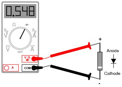
Using a Multimeter
- Set the multimeter to the diode test mode, usually denoted by a diode symbol.
- Connect the red probe to the anode and the black probe to the cathode of the diode.
- The multimeter should display a forward voltage drop (typically around 0.7V for silicon diodes) if the diode is functioning properly.
- Reverse the probes and check that the multimeter displays an open circuit or a very high resistance, indicating that the diode is blocking current in the reverse direction.
Using a Dedicated Diode Tester
- Connect the diode to the tester, ensuring proper polarity (anode to positive, cathode to negative).
- The tester will display the forward voltage drop and indicate if the diode is functioning correctly.
- Reverse the connections and verify that the tester shows an open circuit or high resistance.
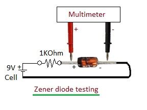
Testing Zener Diodes
Zener diodes are used for voltage regulation and reference. To test a Zener diode, you’ll need a variable DC power supply and a multimeter.
- Set the power supply to a voltage slightly higher than the Zener diode’s rated voltage.
- Connect the Zener diode in reverse bias configuration (cathode to positive, anode to negative) with a Current-limiting resistor in series.
- Measure the voltage across the Zener diode using the multimeter.
- The voltage should be close to the rated Zener voltage if the diode is functioning correctly.
- Vary the power supply voltage and ensure that the Zener voltage remains stable.
Testing Light Emitting Diodes (LEDs)
LEDs are diodes that emit light when forward biased. To test an LED, you can use a multimeter or a simple battery-resistor circuit.
Using a Multimeter
- Set the multimeter to the diode test mode.
- Connect the red probe to the anode (longer lead) and the black probe to the cathode (shorter lead) of the LED.
- The LED should illuminate if it is functioning properly.
- Note the forward voltage drop displayed on the multimeter (typically around 1.8V to 3.3V, depending on the LED color).
Using a Battery-Resistor Circuit
- Connect a current-limiting resistor (typically 220Ω to 1kΩ) in series with the LED.
- Connect the positive terminal of a battery (3V to 9V) to the resistor and the negative terminal to the cathode of the LED.
- The LED should illuminate if it is functioning correctly.
Testing Schottky Diodes
Schottky diodes are used for high-speed switching and have a lower forward voltage drop compared to regular diodes. To test a Schottky diode, you can use a multimeter.
- Set the multimeter to the diode test mode.
- Connect the red probe to the anode and the black probe to the cathode of the Schottky diode.
- The multimeter should display a forward voltage drop (typically around 0.2V to 0.4V) if the diode is functioning properly.
- Reverse the probes and check that the multimeter displays an open circuit or a very high resistance.
Testing Varactor Diodes
Varactor diodes are used for voltage-controlled capacitance in tuning circuits. To test a varactor diode, you’ll need a variable DC power supply, a capacitance meter, and a multimeter.
- Set the power supply to a voltage within the varactor diode’s operating range.
- Connect the varactor diode in reverse bias configuration (cathode to positive, anode to negative).
- Measure the capacitance across the varactor diode using the capacitance meter.
- Vary the power supply voltage and observe the change in capacitance.
- The capacitance should change as the voltage changes, indicating that the varactor diode is functioning correctly.

Common Diode Testing Pitfalls
While testing diodes, there are a few common pitfalls to be aware of:
- Incorrect Polarity: Always ensure that you connect the diode with the correct polarity during testing. Reverse polarity can damage the diode or provide misleading results.
- Insufficient Current Limiting: When testing LEDs or Zener diodes, always use a current-limiting resistor to prevent excessive current flow, which can damage the diode.
- Electrostatic Discharge (ESD): Diodes, especially Schottky and varactor diodes, are sensitive to ESD. Use proper ESD precautions, such as grounding yourself and using ESD-safe tools, when handling and testing these diodes.
- Misinterpreting Results: Be cautious when interpreting the results of diode tests. A diode that passes the test may still have issues such as leakage current or high forward voltage drop. Always consider the specific requirements of your application.
Frequently Asked Questions (FAQ)
-
Q: Can I use a regular multimeter to test all types of diodes?
A: While a regular multimeter with a diode test mode can be used for testing most diodes, it may not provide accurate results for specialized diodes like Zener or varactor diodes. For these types, it’s better to use dedicated test equipment or specific testing circuits. -
Q: What should I do if a diode fails the testing?
A: If a diode fails the testing, it is likely defective and should be replaced. However, before replacing the diode, double-check your testing setup and ensure that you have followed the correct testing procedure for the specific type of diode. -
Q: Can I test a diode while it is still in the circuit?
A: It is generally not recommended to test a diode while it is still in the circuit. Other components in the circuit can affect the test results and may even damage the diode or the testing equipment. It’s best to remove the diode from the circuit before testing. -
Q: How do I identify the anode and cathode of an unmarked diode?
A: For unmarked diodes, you can identify the anode and cathode by visual inspection. The cathode is typically marked with a band, a dot, or a square. If there are no markings, you can use a multimeter’s diode test mode to determine the polarity. The multimeter will display a forward voltage drop when the red probe is connected to the anode and the black probe to the cathode. -
Q: What is the difference between a forward voltage drop and a reverse breakdown voltage?
A: The forward voltage drop is the voltage across a diode when it is conducting current in the forward direction. This voltage is typically around 0.7V for silicon diodes and 0.2V to 0.4V for Schottky diodes. The reverse breakdown voltage, on the other hand, is the voltage at which a diode starts conducting current in the reverse direction. This voltage is usually much higher than the forward voltage drop and is a characteristic of Zener diodes, which are designed to operate in the reverse breakdown region for voltage regulation.
Conclusion
Diode testing is a crucial skill for anyone working with electronic circuits. By understanding the different types of diodes and their corresponding testing techniques, you can ensure the proper functioning of your circuits and troubleshoot any issues that may arise. Remember to always follow the appropriate testing procedures, use the correct equipment, and take necessary precautions to avoid damaging the diodes or the testing equipment.
With this comprehensive guide, you should now have a solid foundation in diode testing techniques. However, keep in mind that this is just the beginning. As you work with more complex circuits and specialized diodes, you may need to adapt and expand your testing skills. Stay curious, keep learning, and don’t hesitate to consult additional resources or seek guidance from experienced professionals when needed.
Happy diode testing!
No responses yet