DIAC Overview
A DIAC, or Diode for Alternating Current, is a two-terminal bidirectional semiconductor device that conducts current only after its breakover voltage has been reached momentarily. Once in conduction mode, the DIAC continues to conduct until the current through it drops below a value characteristic for the device. The DIAC is widely used for triggering thyristors and TRIACs in phase control and AC switching applications.
Key Characteristics of DIACs
- Bidirectional operation
- High dynamic resistance until breakover voltage is reached
- Low dynamic resistance once conducting
- Triggers at a specific breakover voltage in either polarity
- Continues conducting until current drops below holding current
- Used mainly for thyristor and TRIAC triggering circuits
DIAC Construction
DIAC Fabrication Process
DIACs are fabricated using a five-layer silicon PNPNP structure. The manufacturing process involves:
- Starting with an N-type silicon wafer
- Creating P-type regions on both sides using diffusion or ion implantation
- Creating N-type regions over the P-type regions
- Depositing metal contacts on both ends for electrical connections
- Encapsulating the device in an insulating package
The resulting structure has three P-N junctions, with the middle N-region having a higher resistivity than the outer N-regions.
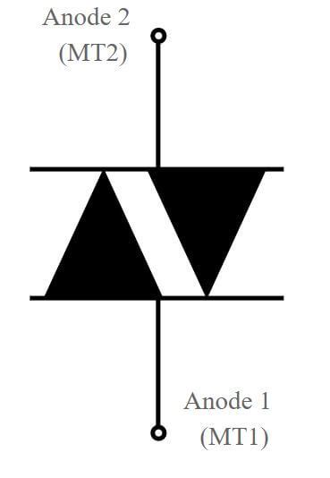
DIAC Symbol and Package
The schematic symbol for a DIAC is:
     |-|
----|   |----
     |-|
DIACs are available in small plastic packages like the DO-35 or SOT-23, suitable for PCB mounting. The two terminals are simply labeled as Anode 1 and Anode 2 or Main Terminal 1 (MT1) and Main Terminal 2 (MT2), as the device is symmetrical.

DIAC Operation
DIAC V-I Characteristics
The voltage-current characteristics of a DIAC look similar to two back-to-back Zener diodes:
Key points on the V-I curve:
- ±VBO: Breakover voltage in forward and reverse directions
- ±IH: Holding current in forward and reverse directions
- ±IS: Reverse leakage current before breakover
The DIAC has a high impedance (off state) until the applied voltage exceeds the breakover voltage in either direction. At this point, the device switches rapidly to a low-impedance state (on state) and conducts current, maintaining a nearly constant voltage drop. The DIAC remains in the on state until the current drops below the holding current value, at which point it switches back to the high-impedance off state.
Breakover Voltage and Holding Current
The breakover voltage (VBO) is the critical parameter that determines the DIAC’s triggering point. It is typically in the range of 20V to 40V, with 32V being a common value. The holding current (IH) is usually a few milliamperes and represents the minimum current required to maintain conduction.
Manufacturers specify these values with a tolerance, e.g.:
| Parameter | Symbol | Min | Typ | Max | Unit |
|---|---|---|---|---|---|
| Breakover Voltage | VBO | 28 | 32 | 36 | V |
| Holding Current | IH | – | 2 | 10 | mA |
The exact values depend on the DIAC type and manufacturer.
Switching Characteristics
DIACs have very fast switching characteristics, transitioning from the off state to on state within tens of nanoseconds when the breakover voltage is exceeded. This rapid switching behavior makes DIACs well-suited for generating sharp trigger pulses for thyristors and TRIACs.
The dynamic resistance of the DIAC is also important:
- High resistance (tens of kilohms) in the off state to block current flow
- Low resistance (few ohms) in the on state for efficient current conduction
These resistance values are often specified in datasheets for specific current levels.

DIAC Applications
Thyristor and TRIAC Triggering
The primary application of DIACs is in triggering circuits for thyristors and TRIACs used in AC power control and switching. A typical circuit configuration is:
         MT2
          │
          │
          ├───── TRIAC Gate
          │
          │
         ┌┴┐
  AC ───┤  ├─── Load ─── AC
         └┬┘
          │
          │ MT1
          ├──┬───────┐
          │  │       │
          │  └─ R ───┘
          │  DIAC
          │
         ─┴─ C
          │
In this circuit:
- The AC voltage charges the capacitor C through resistor R.
- When the capacitor voltage reaches the DIAC’s breakover voltage, the DIAC conducts and discharges the capacitor into the TRIAC’s gate.
- The TRIAC is triggered and conducts current to the load.
- The capacitor begins charging again, and the cycle repeats on alternate half-cycles of the AC waveform.
By adjusting the R-C time constant, the firing angle of the TRIAC can be controlled, allowing for AC power regulation.
Other variations of this basic triggering circuit are used for different types of thyristors (SCRs, PUTs) and in specific applications like motor speed controls, light dimmers, and temperature controllers.
Zero-Crossing Detectors
DIACs can also be used in zero-crossing detector circuits due to their symmetric Bidirectional Switching characteristics. A zero-crossing detector produces a pulse whenever the AC voltage passes through zero. This is useful for synchronizing control circuits to the AC mains.
A basic zero-crossing detector using a DIAC looks like:
               DIAC
               ┌───┐
               │   │
              ┌┴┐ ┌┴┐
  AC ───────┬┤  ├┤  ├┬──────────┐
            │└┬┘ └┬┘│          │
            │ │   │ │          │
            │ └───┘ │          │
            │       │          │
            └──┬┬───┘         ─┴─
               ││             GND
               ││ Output
               ││ Pulses
               ││
              ─┴┴─
              GND
Here, the DIAC conducts briefly whenever the AC voltage exceeds its breakover voltage in either polarity, producing narrow pulses at the zero-crossings of the AC waveform. These pulses can be used to trigger or synchronize other circuits.

DIAC Selection and Usage Tips
When selecting a DIAC for a specific application:
- Choose a DIAC with a breakover voltage suitable for the desired triggering point in your circuit.
- Ensure the DIAC’s maximum ratings (current, power dissipation) are not exceeded in your application.
- Consider the DIAC’s packaging and mounting requirements for your PCB design.
- Use the DIAC in series with current-limiting resistors to protect the device and control the trigger pulse characteristics.
- Be aware of the DIAC’s temperature dependence; the breakover voltage and holding current can vary with ambient temperature.
Always refer to the manufacturer’s datasheets for detailed specifications, ratings, and application guidance for the specific DIAC you are using.
Frequently Asked Questions (FAQ)
1. What is the difference between a DIAC and a Zener diode?
While a DIAC and two back-to-back Zener diodes may look similar in their V-I curves, they have some key differences:
- A DIAC is a bidirectional device, while a Zener diode is unidirectional.
- A DIAC has a symmetrical breakover voltage in both polarities, while Zener diodes have a specific Zener voltage in one direction only.
- DIACs are used primarily for triggering thyristors and TRIACs, while Zener diodes are used for voltage regulation and protection.
2. Can a DIAC be used as a voltage regulator?
No, DIACs are not suitable for voltage regulation due to their negative resistance characteristic once in conduction. Zener diodes and voltage regulator ICs are better choices for voltage regulation applications.
3. How do I choose the right DIAC for my application?
The main criteria for selecting a DIAC are:
- Breakover voltage (VBO): Choose a value that suits your desired triggering point.
- Maximum current and power dissipation ratings: Ensure these are not exceeded in your circuit.
- Package type: Choose a package that fits your PCB layout and assembly process.
Always consult the DIAC manufacturer’s datasheets for detailed specifications and ratings.
4. What happens if I exceed the DIAC’s maximum ratings?
Exceeding a DIAC’s maximum voltage, current, or power dissipation ratings can lead to device failure or degraded performance over time. Use current-limiting resistors in series with the DIAC and ensure your circuit operates within the device’s rated limits.
5. Can I use a DIAC for DC applications?
DIACs are designed primarily for AC circuits and applications. While they can be used in certain DC triggering circuits, their characteristics are not optimized for DC operation. Other devices like transistors, SCRs, or UJTs are often more suitable for DC switching and triggering applications.
No responses yet