Introduction to Microstrip Ring Resonators
Microstrip ring resonators are widely used structures for characterizing the dielectric properties of printed circuit board (PCB) materials. These resonators are compact, easy to fabricate, and provide accurate measurements of the dielectric constant and dissipation factor of the substrate material. In this article, we will discuss the theory behind microstrip ring resonators, their design considerations, and the experimental setup for measuring the dielectric properties of a PCB material.
Theory of Microstrip Ring Resonators
A microstrip ring resonator consists of a circular or square-shaped microstrip transmission line that is coupled to two feed lines. The resonator is designed to support standing wave patterns at specific frequencies, known as resonant frequencies. The resonant frequencies are determined by the geometry of the resonator and the dielectric properties of the substrate material.
The resonant frequency of a microstrip ring resonator is given by:
$f_n = \frac{nc}{2\pi r \sqrt{\epsilon_{eff}}}$
where:
– $f_n$ is the nth resonant frequency
– $c$ is the speed of light in vacuum
– $r$ is the mean radius of the resonator
– $\epsilon_{eff}$ is the effective dielectric constant of the substrate material
The effective dielectric constant ($\epsilon_{eff}$) is a function of the substrate’s dielectric constant ($\epsilon_r$) and the geometry of the microstrip line. It can be approximated using the following equation:
$\epsilon_{eff} = \frac{\epsilon_r + 1}{2} + \frac{\epsilon_r – 1}{2}\left(1 + \frac{12h}{w}\right)^{-\frac{1}{2}}$
where:
– $h$ is the thickness of the substrate
– $w$ is the width of the microstrip line
Design Considerations for Microstrip Ring Resonators
When designing a microstrip ring resonator, several factors must be considered to ensure accurate measurements of the dielectric properties. These include:
-
Resonator geometry: The resonator can be circular or square-shaped. Circular resonators are more commonly used due to their simpler analysis and more uniform current distribution.
-
Coupling gaps: The coupling gaps between the feed lines and the resonator should be carefully designed to achieve critical coupling, which results in maximum power transfer and sharp resonance peaks.
-
Substrate thickness: The substrate thickness should be chosen to minimize conductor losses and radiation losses while maintaining a reasonable line width for fabrication.
-
Resonator size: The size of the resonator should be selected based on the desired resonant frequency range and the available PCB area.
Experimental Setup for Dielectric Property Measurement
To measure the dielectric constant and dissipation factor of a PCB material using a microstrip ring resonator, the following experimental setup is required:
-
Vector Network Analyzer (VNA): A VNA is used to measure the scattering parameters (S-parameters) of the resonator. The S-parameters provide information about the resonant frequencies and quality factors of the resonator.
-
Calibration kit: A calibration kit is necessary to remove the effects of the connectors and cables from the measured S-parameters. This ensures accurate measurements of the resonator’s response.
-
Test fixture: A test fixture is used to hold the PCB with the microstrip ring resonator and provide a stable connection to the VNA.
-
PCB with microstrip ring resonator: The PCB with the fabricated microstrip ring resonator is the device under test (DUT).
Measurement Procedure
-
Calibrate the VNA using the calibration kit to remove the effects of the connectors and cables.
-
Place the PCB with the microstrip ring resonator in the test fixture and connect it to the VNA.
-
Measure the S-parameters of the resonator over a frequency range that includes the desired resonant frequencies.
-
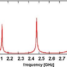
Identify the resonant frequencies from the measured S-parameters. The resonant frequencies correspond to the peaks in the magnitude of the transmission coefficient (S21).
-
Measure the quality factor (Q) of each resonance peak. The quality factor is related to the dissipation factor (tan δ) of the substrate material by:
$Q = \frac{1}{\tan \delta}$
-
Calculate the effective dielectric constant ($\epsilon_{eff}$) using the measured resonant frequencies and the resonator geometry.
-
Determine the dielectric constant ($\epsilon_r$) of the substrate material using the calculated effective dielectric constant and the substrate thickness.

Data Analysis and Results
After measuring the S-parameters of the microstrip ring resonator, the data must be analyzed to extract the dielectric constant and dissipation factor of the substrate material. The following steps outline the data analysis process:
-
Resonant frequency identification: The resonant frequencies are identified from the peaks in the magnitude of the transmission coefficient (S21). These peaks correspond to the standing wave patterns supported by the resonator.
-
Quality factor calculation: The quality factor (Q) of each resonance peak is calculated using the 3 dB bandwidth method. The 3 dB bandwidth is the frequency range over which the power of the resonance peak drops by 3 dB from its maximum value. The quality factor is given by:
$Q = \frac{f_0}{\Delta f_{3dB}}$
where:
– $f_0$ is the resonant frequency
– $\Delta f_{3dB}$ is the 3 dB bandwidth
- Dissipation factor determination: The dissipation factor (tan δ) is calculated using the quality factor:
$\tan \delta = \frac{1}{Q}$
- Effective dielectric constant calculation: The effective dielectric constant ($\epsilon_{eff}$) is calculated using the measured resonant frequencies and the resonator geometry. For a circular microstrip ring resonator, the effective dielectric constant is given by:
$\epsilon_{eff} = \left(\frac{nc}{2\pi r f_n}\right)^2$
where:
– $n$ is the resonance mode number
– $c$ is the speed of light in vacuum
– $r$ is the mean radius of the resonator
– $f_n$ is the nth resonant frequency
- Dielectric constant determination: The dielectric constant ($\epsilon_r$) of the substrate material is determined using the calculated effective dielectric constant and the substrate thickness. An iterative method or a closed-form expression can be used to solve for the dielectric constant.
The table below shows an example of the measured resonant frequencies, calculated quality factors, dissipation factors, and effective dielectric constants for a microstrip ring resonator:
| Mode (n) | Resonant Frequency (GHz) | Quality Factor (Q) | Dissipation Factor (tan δ) | Effective Dielectric Constant ($\epsilon_{eff}$) |
|---|---|---|---|---|
| 1 | 2.45 | 150 | 0.0067 | 4.2 |
| 2 | 4.90 | 180 | 0.0056 | 4.1 |
| 3 | 7.35 | 200 | 0.0050 | 4.0 |
From the calculated effective dielectric constants, the dielectric constant of the substrate material can be determined. In this example, the average dielectric constant of the substrate is found to be approximately 4.5.

Conclusion
Microstrip ring resonators provide a simple and accurate method for characterizing the dielectric properties of PCB materials. By measuring the resonant frequencies and quality factors of the resonator, the dielectric constant and dissipation factor of the substrate material can be determined. This information is crucial for designing high-frequency circuits and ensuring the performance of PCBs in various applications.
The experimental setup for measuring the dielectric properties using a microstrip ring resonator involves a VNA, calibration kit, test fixture, and the PCB with the fabricated resonator. The measured S-parameters are analyzed to extract the resonant frequencies, quality factors, dissipation factors, and effective dielectric constants. From these values, the dielectric constant of the substrate material can be determined.
Accurate knowledge of the dielectric properties of PCB materials is essential for the development of high-speed digital circuits, microwave devices, and antennas. Microstrip ring resonators offer a reliable and cost-effective solution for characterizing these properties, enabling engineers to optimize their designs and improve the performance of electronic systems.

Frequently Asked Questions (FAQ)
-
What is a microstrip ring resonator?
A microstrip ring resonator is a circular or square-shaped microstrip transmission line that is coupled to two feed lines. It is used to characterize the dielectric properties of PCB materials by measuring its resonant frequencies and quality factors. -
How does a microstrip ring resonator work?
A microstrip ring resonator supports standing wave patterns at specific frequencies, known as resonant frequencies. These frequencies depend on the geometry of the resonator and the dielectric properties of the substrate material. By measuring the resonant frequencies and quality factors, the dielectric constant and dissipation factor of the substrate can be determined. -
What equipment is needed to measure the dielectric properties using a microstrip ring resonator?
To measure the dielectric properties using a microstrip ring resonator, you need a Vector Network Analyzer (VNA), a calibration kit, a test fixture, and the PCB with the fabricated microstrip ring resonator. -
How are the dielectric constant and dissipation factor calculated from the measured data?
The dielectric constant and dissipation factor are calculated from the measured resonant frequencies and quality factors of the microstrip ring resonator. The effective dielectric constant is first calculated using the resonant frequencies and resonator geometry. Then, the dielectric constant of the substrate material is determined using the effective dielectric constant and substrate thickness. The dissipation factor is calculated from the quality factor of the resonance peaks. -
What are the advantages of using a microstrip ring resonator for dielectric property characterization?
Microstrip ring resonators offer several advantages for dielectric property characterization, including: - Simple and compact design
- Easy fabrication using standard PCB manufacturing techniques
- Accurate measurement of dielectric constant and dissipation factor
- Non-destructive testing of PCB materials
- Cost-effective solution compared to other methods
No responses yet