What is a DC Motor?
A DC (Direct Current) motor is an electrical machine that converts electrical energy into mechanical energy. It operates on direct current power and is one of the most commonly used types of motors in various applications, from small household appliances to large industrial machinery.
DC motors consist of two main components: the stator (stationary part) and the rotor (rotating part). The stator includes permanent magnets or electromagnetic windings that generate a magnetic field, while the rotor is an armature with windings that carry current. When current flows through the rotor windings, it creates a magnetic field that interacts with the stator’s field, causing the rotor to spin.
How Does a DC Motor Work?
The working principle of a DC motor is based on the interaction between magnetic fields and electric currents. It relies on the following fundamental concepts:
- Magnetic fields: Permanent magnets or electromagnets create a stationary magnetic field in the stator.
- Electric current: Current flowing through the rotor windings generates a magnetic field around the rotor.
- Lorentz force: The interaction between the stator’s magnetic field and the rotor’s magnetic field produces a force (Lorentz force) that causes the rotor to rotate.
The direction of rotation depends on the direction of the current in the rotor windings and the polarity of the stator’s magnetic field. By reversing either the current direction or the magnetic field polarity, the motor’s rotation direction can be changed.
To maintain continuous rotation, a commutator and brushes are used to periodically reverse the current direction in the rotor windings as the rotor spins. This ensures that the rotor’s magnetic field always experiences a torque in the same direction, allowing for continuous rotation.

Types of DC Motors
There are several types of DC motors, each with unique characteristics and applications:
- Brushed DC Motors:
- Permanent Magnet DC Motor (PMDC)
- Series DC Motor
- Shunt DC Motor
- Compound DC Motor
- Brushless DC Motors (BLDC)
- Stepper Motors
- Servo Motors
Brushed DC Motors
Brushed DC motors are the most common type of DC motor. They use a mechanical commutator and brushes to reverse the current direction in the rotor windings. The commutator consists of a series of conductive segments connected to the rotor windings, while the brushes are conductive contacts that press against the commutator.
As the rotor spins, the brushes slide over the commutator segments, continuously switching the current direction in the rotor windings. This process ensures a unidirectional torque on the rotor, enabling continuous rotation.
Brushed DC motors are further classified based on how the stator’s magnetic field is generated and how the rotor windings are connected:
-
Permanent Magnet DC Motor (PMDC): The stator consists of permanent magnets that provide a constant magnetic field. The rotor windings are connected to the commutator, and the brushes supply current to the rotor.
-
Series DC Motor: The stator and rotor windings are connected in series. The same current flows through both windings, creating a strong magnetic field and high starting torque. Series DC motors are suitable for applications requiring high starting torque, such as electric starters in automobiles.
-
Shunt DC Motor: The stator and rotor windings are connected in parallel. The stator winding (field winding) is connected directly to the power supply, while the rotor winding (armature winding) is connected to the power supply through the brushes and commutator. Shunt DC motors offer good speed regulation and are used in applications requiring constant speed under varying loads.
-
Compound DC Motor: This motor combines the characteristics of series and shunt motors. It has both series and shunt field windings, providing a compromise between the high starting torque of series motors and the good speed regulation of shunt motors. Compound DC motors are used in applications that require a balance of torque and speed control.
Brushless DC Motors (BLDC)
Brushless DC (BLDC) motors eliminate the need for a mechanical commutator and brushes. Instead, they use electronic commutation to control the current in the stator windings. The rotor consists of permanent magnets, while the stator has multiple windings.
The electronic controller continuously switches the current in the stator windings based on the rotor’s position, which is typically determined by Hall effect sensors or back-EMF sensing. This creates a rotating magnetic field that interacts with the rotor’s permanent magnets, causing the rotor to spin.
BLDC motors offer several advantages over brushed DC motors:
- Higher efficiency due to the absence of brush friction and commutator losses
- Longer lifespan as there are no brushes to wear out
- Lower maintenance requirements
- Higher speed and torque capabilities
- Quieter operation
BLDC motors are widely used in applications that require high performance, efficiency, and reliability, such as electric vehicles, drones, and computer hard drives.
Stepper Motors
Stepper motors are a type of brushless DC motor that moves in discrete steps. They consist of a rotor with permanent magnets and a stator with multiple windings. By energizing the stator windings in a specific sequence, the rotor can be precisely positioned at fixed angular increments.
Stepper motors are commonly used in applications that require precise position control, such as 3D printers, CNC machines, and robotics. They offer excellent low-speed torque and can hold their position even when powered off.
Servo Motors
Servo motors are a type of DC motor that incorporates a closed-loop control system for precise position, speed, or torque control. They consist of a DC motor, a position sensor (such as an encoder or potentiometer), and a control circuit.
The control circuit continuously compares the desired position or speed with the actual position or speed measured by the sensor. It then adjusts the motor’s input to minimize the error, ensuring accurate and responsive control.
Servo motors are widely used in robotics, automation systems, and control applications where precise motion control is critical.

DC Motor Specifications and Parameters
When selecting or working with DC motors, several key specifications and parameters need to be considered:
-
Voltage Rating: The nominal voltage at which the motor is designed to operate. Operating the motor at a different voltage can affect its performance and lifespan.
-
Current Rating: The maximum continuous current the motor can handle without overheating or damaging the windings.
-
Power Rating: The mechanical output power the motor can deliver, usually expressed in watts (W) or horsepower (hp).
-
Speed: The rotational speed of the motor, typically expressed in revolutions per minute (RPM). The speed can be no-load speed (without any load attached) or rated speed (at the rated load).
-
Torque: The rotational force produced by the motor, usually expressed in Newton-meters (N·m) or pound-force-feet (lbf·ft). The torque can be starting torque (at zero speed), rated torque (at the rated speed), or stall torque (the maximum torque the motor can produce at zero speed without damage).
-
Efficiency: The ratio of the motor’s output mechanical power to its input electrical power, expressed as a percentage. Higher efficiency motors convert a larger portion of the input power into useful mechanical work.
-
Inductance: The property of the motor windings that opposes changes in current. It affects the motor’s dynamic response and can be important in applications with frequent speed or direction changes.
-
Resistance: The electrical resistance of the motor windings, which determines the current draw and power dissipation.
-
Inertia: The motor’s resistance to changes in rotational speed. A higher inertia results in slower acceleration and deceleration.
These specifications and parameters are typically provided in the motor’s datasheet or by the manufacturer. Understanding and properly matching these characteristics to the application requirements is crucial for optimal motor selection and performance.

DC Motor Control Methods
Controlling the speed, torque, or position of a DC motor is essential in many applications. Several control methods can be employed depending on the motor type and the specific requirements:
-
Voltage Control: Varying the voltage applied to the motor using a variable power supply or a voltage regulator. Higher voltages result in higher speeds, while lower voltages reduce the speed. This method is simple but may not provide precise speed control, especially under varying loads.
-
PWM (Pulse Width Modulation) Control: Applying a pulsed voltage signal to the motor, where the pulse width determines the effective voltage. By varying the duty cycle of the PWM signal, the motor speed can be controlled. PWM control offers better efficiency and more precise speed control compared to voltage control.
-
Current Control: Regulating the current flowing through the motor windings to control the torque. This method is commonly used in torque-critical applications or when precise torque control is required.
-
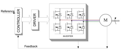
Closed-Loop Control: Incorporating feedback from sensors (e.g., encoders, tachometers) to continuously monitor the motor’s speed, position, or torque. The control system compares the feedback with the desired setpoint and adjusts the motor input accordingly. Closed-loop control provides the most accurate and responsive control but requires additional hardware and complexity.
-
Field-Oriented Control (FOC): An advanced control technique used primarily with BLDC motors. FOC controls the magnetic field orientation in the motor to optimize torque production and efficiency. It offers superior performance and dynamic response but requires complex algorithms and processing power.
The choice of control method depends on the specific application requirements, such as speed range, load variations, precision, and dynamic response. Proper control ensures optimal motor performance, efficiency, and reliability.
Applications of DC Motors
DC motors find applications across a wide range of industries and products due to their versatility, reliability, and controllability. Some common applications include:
- Automotive: Starters, windshield wipers, power windows, seat adjustments, and cooling fans.
- Robotics: Actuators for robotic arms, grippers, and mobile robots.
- Industrial Automation: Conveyor systems, packaging machines, CNC machines, and 3D printers.
- Consumer Electronics: Disk drives, printers, toys, and small appliances.
- Medical Equipment: Surgical tools, pumps, and prosthetics.
- Aerospace: Control surfaces, landing gear, and fuel pumps.
- Home Appliances: Blenders, mixers, vacuum cleaners, and washing machines.
- Power Tools: Drills, saws, sanders, and grinders.
- HVAC Systems: Fans, blowers, and compressors.
- Electric Vehicles: Propulsion motors and auxiliary systems.
The choice of DC motor type and specifications depends on the specific application requirements, such as torque, speed, efficiency, size, and environmental conditions.
Advantages and Disadvantages of DC Motors
DC motors offer several advantages that make them popular in various applications:
- Simple control: DC motors can be easily controlled using simple voltage or PWM techniques, making them suitable for a wide range of applications.
- High starting torque: Many DC motor types, such as series and permanent magnet motors, provide high starting torque, which is beneficial in applications requiring quick starts or heavy loads.
- Wide speed range: DC motors can operate over a wide range of speeds, from zero to their rated speed, by varying the applied voltage or using speed control techniques.
- Compact size: DC motors are available in a variety of sizes, including small and compact designs, making them suitable for space-constrained applications.
- Reversibility: The direction of rotation can be easily reversed by changing the polarity of the applied voltage.
However, DC motors also have some disadvantages:
- Brushes and commutator wear: In brushed DC motors, the brushes and commutator are subject to wear and tear, requiring periodic maintenance and replacement.
- Sparking and electromagnetic interference (EMI): The commutation process in brushed DC motors can cause sparking and generate EMI, which may interfere with nearby electronic devices.
- Limited high-speed operation: The presence of brushes and the commutator in brushed DC motors limits their maximum speed due to mechanical limitations and brush bounce.
- Lower efficiency: Brushed DC motors generally have lower efficiency compared to brushless DC motors due to losses in the brushes and commutator.
- Higher cost: Some types of DC motors, such as brushless DC and servo motors, can be more expensive compared to their AC counterparts due to the added complexity and control electronics.
Despite these disadvantages, DC motors remain a popular choice for many applications due to their simplicity, controllability, and wide range of available types and sizes.
Maintenance and Troubleshooting of DC Motors
Proper maintenance and timely troubleshooting are essential to ensure the reliable and efficient operation of DC motors. Here are some key aspects of DC motor maintenance and troubleshooting:
-
Regular Inspection: Periodically inspect the motor for signs of wear, damage, or contamination. Check for unusual noises, vibrations, or overheating during operation.
-
Lubrication: For motors with bearings, ensure proper lubrication as per the manufacturer’s recommendations. Use the specified lubricant and avoid over-lubrication, which can cause grease buildup and attract dirt.
-
Brush and Commutator Maintenance: In brushed DC motors, regularly check the brushes for wear and replace them when necessary. Inspect the commutator for signs of damage, pitting, or uneven wear. Clean the commutator with a commutator cleaning solution or fine sandpaper to maintain a smooth surface.
-
Winding Insulation: Check the motor windings for any signs of insulation damage or deterioration. Damaged insulation can lead to short circuits and motor failure.
-
Connections and Wiring: Ensure all electrical connections are tight and free from corrosion. Check for any frayed or damaged wiring and replace as needed.
-
Ventilation and Cooling: Keep the motor’s ventilation openings clean and unobstructed to ensure proper cooling. Remove any dust, dirt, or debris that may hinder airflow.
-
Overload Protection: Verify that the motor is protected against overloads using appropriate fuses, circuit breakers, or thermal overload relays.
When troubleshooting DC motor issues, consider the following steps:
-
Check Power Supply: Verify that the motor is receiving the correct voltage and current. Use a multimeter to measure the voltage and current and compare them with the motor’s specifications.
-
Inspect Connections: Check all electrical connections for looseness, corrosion, or damage. Ensure proper contact between the brushes and commutator in brushed motors.
-
Mechanical Issues: Check for any mechanical obstructions or binding that may prevent the motor from rotating freely. Inspect the coupling, belts, or gears for proper alignment and tension.
-
Bearing Condition: Assess the condition of the motor bearings. Worn or damaged bearings can cause increased friction, noise, and vibration.
-
Winding Resistance: Measure the resistance of the motor windings using a multimeter and compare it with the specified values. Deviations may indicate winding damage or short circuits.
-
Commutator and Brush Condition: In brushed motors, inspect the commutator for signs of damage, pitting, or uneven wear. Check the brushes for excessive wear or improper seating.
-
Control System: Verify that the motor control system, including any speed controllers, drivers, or feedback devices, is functioning correctly and sending appropriate signals to the motor.
By following a regular maintenance schedule and promptly addressing any issues through systematic troubleshooting, you can maximize the performance, reliability, and lifespan of your DC motors.
FAQ
-
What is the difference between brushed and brushless DC motors?
Brushed DC motors use mechanical brushes and a commutator to switch the current direction in the rotor windings, while brushless DC motors use electronic commutation and have permanent magnets on the rotor. Brushless motors offer higher efficiency, longer lifespan, and less maintenance compared to brushed motors. -
Can I use a DC motor with an AC power supply?
No, DC motors are designed to operate on direct current (DC) power. Using an AC power supply directly with a DC motor can damage the motor. However, you can use a rectifier or an AC-to-DC converter to convert AC power to DC power suitable for the motor. -
How do I control the speed of a DC motor?
There are several methods to control the speed of a DC motor, including: - Voltage control: Varying the voltage applied to the motor using a variable power supply or voltage regulator.
- PWM (Pulse Width Modulation) control: Applying a pulsed voltage signal to the motor and varying the pulse width to control the effective voltage.
-
Closed-loop control: Using feedback from sensors to monitor the motor’s speed and adjusting the input accordingly.
-
What is the purpose of the commutator in a brushed DC motor?
The commutator in a brushed DC motor is responsible for reversing the current direction in the rotor windings as the rotor spins. It consists of a series of conductive segments connected to the rotor windings. As the brushes slide over the commutator segments, they continuously switch the current
No responses yet