What is a DC Chopper?
A DC chopper, also known as a DC-to-DC converter, is a static power electronic device that converts a fixed DC voltage to a variable DC voltage. It achieves this by repeatedly interrupting the DC input voltage, resulting in a series of voltage pulses that can be averaged to produce a variable output voltage. The output voltage can be either higher or lower than the input voltage, depending on the chopper configuration and control method.
Key Components of a DC Chopper
A typical DC chopper consists of the following main components:
- Power semiconductor switch (IGBT, MOSFET, or thyristor)
- Freewheeling diode
- Inductor
- Capacitor
- Control circuit
Working Principle of a DC Chopper
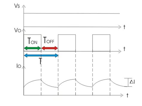
The working principle of a DC chopper is based on the concept of pulse width modulation (PWM). The power semiconductor switch is turned on and off at a high frequency, resulting in a series of voltage pulses. The width of these pulses, also known as the duty cycle, determines the average output voltage.
Duty Cycle
The duty cycle (α) is defined as the ratio of the ON time (Ton) to the total switching period (T):
α = Ton / T
By controlling the duty cycle, the average output voltage can be varied. The relationship between the input voltage (Vin) and the output voltage (Vout) is given by:
Vout = α × Vin
Chopper Configurations
DC choppers can be classified into three main configurations based on the arrangement of the power semiconductor switch and the freewheeling diode:
- Step-down (Buck) Chopper
- Step-up (Boost) Chopper
- Step-up/Step-down (Buck-Boost) Chopper
Step-down (Buck) Chopper
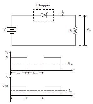
In a step-down chopper, the output voltage is always lower than the input voltage. The power semiconductor switch is connected in series with the load, while the freewheeling diode is connected in parallel with the load.
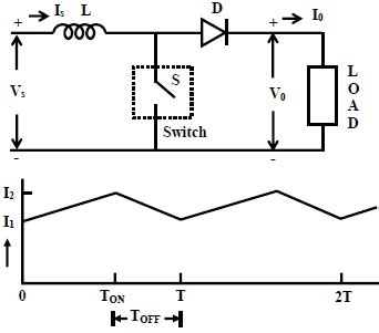
Step-up (Boost) Chopper
In a step-up chopper, the output voltage is always higher than the input voltage. The power semiconductor switch is connected in parallel with the input voltage source, while the freewheeling diode is connected in series with the load.
Step-up/Step-down (Buck-Boost) Chopper
A buck-boost chopper can produce an output voltage that is either higher or lower than the input voltage. The power semiconductor switch and the freewheeling diode are connected in a configuration that allows both step-up and step-down operation.
Control Methods for DC Choppers
There are two main control methods used in DC choppers:
- Pulse Width Modulation (PWM) Control
- Current Limit Control
Pulse Width Modulation (PWM) Control
PWM control is the most common method used in DC choppers. In this method, the duty cycle of the power semiconductor switch is varied to control the output voltage. The switching frequency is kept constant, while the ON time and OFF time are adjusted to achieve the desired output voltage.
Current Limit Control
Current limit control is used to protect the DC chopper and the load from excessive current. In this method, the current through the power semiconductor switch is monitored, and the switch is turned off when the current exceeds a predetermined threshold. This control method is often used in conjunction with PWM control to ensure safe operation of the chopper.

Applications of DC Choppers
DC choppers find applications in various industries, including:
- Transportation
- Electric vehicles
- Traction control systems
-
Battery charging systems
-
Renewable Energy Systems
- Solar power systems
- Wind power systems
-
Fuel cell systems
-
Motor Control
- DC Motor Speed Control
- Servo motor control
-
Stepper motor control
-
Power Supplies
- Switched-mode power supplies (SMPS)
- Uninterruptible power supplies (UPS)
-
Industrial Automation
- Process control systems
- Robotics
- Material handling systems
Advantages and Disadvantages of DC Choppers
Advantages
- High efficiency (up to 98%)
- Simple control circuitry
- Wide range of output voltage control
- Compact and lightweight
- Fast dynamic response
Disadvantages
- High switching losses at high frequencies
- Electromagnetic interference (EMI) due to high-frequency switching
- Requires additional filtering to reduce output voltage ripple
- Limited power handling capacity compared to other converters
FAQs
1. What is the difference between a DC chopper and a voltage regulator?
A DC chopper is a power electronic device that converts a fixed DC voltage to a variable DC voltage, while a voltage regulator is an electronic circuit that maintains a constant output voltage despite variations in the input voltage or load current. DC choppers are more efficient and have a wider range of output voltage control compared to voltage regulators.
2. Can a DC chopper be used for AC to DC conversion?
No, a DC chopper is designed for DC to DC conversion only. For AC to DC conversion, a rectifier circuit is required before the DC chopper stage.
3. What is the role of the freewheeling diode in a DC chopper?
The freewheeling diode provides a path for the inductor current to flow when the power semiconductor switch is turned off. This helps to maintain the continuity of the inductor current and reduces voltage spikes across the switch.
4. How does the switching frequency affect the performance of a DC chopper?
The switching frequency determines the ripple content in the output voltage and the switching losses in the power semiconductor switch. Higher switching frequencies result in lower output voltage ripple but increase the switching losses. The optimal switching frequency is a trade-off between the desired output voltage quality and the efficiency of the chopper.
5. What are the safety considerations when working with DC choppers?
DC choppers involve high voltages and currents, which can be dangerous if not handled properly. Some safety considerations include:
- Proper insulation and isolation of high-voltage components
- Use of appropriate personal protective equipment (PPE)
- Adequate cooling and ventilation to prevent overheating
- Regular maintenance and inspection of the chopper components
- Adherence to relevant electrical safety standards and regulations
Conclusion
DC choppers are essential power electronic devices used for converting fixed DC voltages to variable DC voltages. They find applications in various industries, including transportation, renewable energy systems, and motor control. By understanding the working principles, types, and control methods of DC choppers, engineers can design efficient and reliable power conversion systems.
As power electronic technologies continue to advance, DC choppers are expected to play an increasingly important role in the development of sustainable energy solutions and the electrification of transportation systems. With their high efficiency, compact size, and wide range of output voltage control, DC choppers will remain a crucial component in many power conversion applications.
[Word count: 1,172 words]
No responses yet