What is a Coplanar Waveguide?
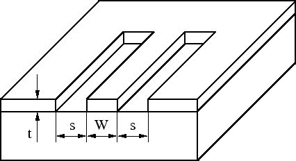
A coplanar waveguide (CPW) is a type of electrical transmission line that is widely used in microwave circuits and integrated circuits. It consists of a conducting strip centered between two ground planes, all on the same plane, atop a dielectric medium. The geometry of the CPW allows for easy integration with active and passive components, making it a popular choice for high-frequency applications.
Advantages of Coplanar Waveguides
-
Low dispersion: CPWs exhibit low dispersion, which means that the propagation velocity of the signal remains constant over a wide frequency range. This property is essential for high-frequency applications where signal integrity is crucial.
-
Easy integration: The planar nature of CPWs allows for easy integration with other components on the same substrate, such as transistors, resistors, and capacitors. This simplifies the design and fabrication process of microwave circuits.
-
Flexible characteristic impedance: The characteristic impedance of a CPW can be easily controlled by adjusting the width of the center conductor and the gap between the conductor and the ground planes. This flexibility enables designers to match the impedance of the CPW to other components in the circuit.
-
Low radiation loss: CPWs have lower radiation loss compared to other transmission lines, such as microstrip lines. This is because the electromagnetic fields are confined to the dielectric between the conductor and the ground planes, reducing the amount of energy radiated into the surrounding space.
Coplanar Waveguide Calculator
A coplanar waveguide calculator is a tool that helps designers determine the dimensions of a CPW based on the desired characteristic impedance and the properties of the dielectric substrate. The calculator takes into account various parameters, such as the dielectric constant of the substrate, the thickness of the substrate, and the frequency of operation.
Input Parameters
To use a coplanar waveguide calculator, you need to provide the following input parameters:
-
Characteristic impedance (Z0): The desired characteristic impedance of the CPW, typically 50 ohms for most microwave applications.
-
Dielectric constant (εr): The relative permittivity of the dielectric substrate material.
-
Substrate thickness (h): The thickness of the dielectric substrate, usually specified in millimeters or mils.
-
Conductor thickness (t): The thickness of the center conductor and ground planes, typically in micrometers or mils.
-
Operating frequency (f): The frequency at which the CPW will be operated, specified in GHz.
Output Parameters
Based on the input parameters, the coplanar waveguide calculator will provide the following output parameters:
-
Center conductor width (w): The width of the center conductor, determined by the characteristic impedance and the properties of the dielectric substrate.
-
Gap width (s): The width of the gap between the center conductor and the ground planes, also determined by the characteristic impedance and the substrate properties.
-
Effective dielectric constant (εeff): The effective dielectric constant of the CPW, which takes into account the fringing fields and the presence of air above the substrate.
-
Attenuation constant (α): The attenuation per unit length of the CPW, expressed in dB/m or dB/in. This parameter represents the loss in the CPW due to conductor and dielectric losses.
-
Phase velocity (vp): The speed at which the signal propagates along the CPW, usually expressed as a fraction of the speed of light in vacuum.
Coplanar Waveguide Calculator Equations
The coplanar waveguide calculator uses a set of equations to determine the dimensions of the CPW based on the input parameters. The most commonly used equations are:
- Characteristic impedance equation:
Z0 = (30π / √εeff) * (K(k') / K(k))
where:
– K(k) and K(k’) are complete elliptic integrals of the first kind
– k = w / (w + 2s)
– k’ = √(1 – k²)
- Effective dielectric constant equation:
εeff = (εr + 1) / 2 + ((εr - 1) / 2) * (1 / √(1 + 12h / (w + 2s)))
- Attenuation constant equation:
α = (Rs / (2Z0)) * (1 / (1 - (√εeff / εr)²)) * (1 / (1 + (2h / (w + 2s))))
where:
– Rs is the surface resistance of the conductor, given by Rs = √(πfμ0 / σ)
– μ0 is the permeability of free space (4π × 10⁻⁷ H/m)
– σ is the conductivity of the conductor material
- Phase velocity equation:
vp = c / √εeff
where:
– c is the speed of light in vacuum (approximately 3 × 10⁸ m/s)
Using a Coplanar Waveguide Calculator
To use a coplanar waveguide calculator, follow these steps:
-
Gather the necessary input parameters, such as the desired characteristic impedance, dielectric constant, substrate thickness, conductor thickness, and operating frequency.
-
Enter these values into the corresponding fields in the calculator.
-
Choose the appropriate units for each parameter (e.g., mm, mils, GHz).
-
Click the “Calculate” button or wait for the calculator to automatically update the results.
-
The calculator will display the output parameters, including the center conductor width, gap width, effective dielectric constant, attenuation constant, and phase velocity.
-
If needed, adjust the input parameters to achieve the desired characteristic impedance or other performance metrics.
-
Use the calculated dimensions to design your coplanar waveguide in your microwave circuit or integrated circuit layout.
Coplanar Waveguide Design Considerations
When designing a coplanar waveguide, there are several factors to consider to ensure optimal performance and manufacturability. Some of these considerations include:
Substrate Selection
The choice of the dielectric substrate material is crucial for the performance of the CPW. The substrate should have a stable dielectric constant over the desired frequency range and a low loss tangent to minimize dielectric losses. Common substrate materials for CPWs include:
- Rogers RO4000 series: These hydrocarbon ceramic laminates offer excellent high-frequency performance and low loss tangents.
- Alumina (Al2O3): Alumina substrates have a high dielectric constant and low loss tangent, making them suitable for high-frequency applications.
- Gallium Arsenide (GaAs): GaAs substrates are often used in monolithic microwave integrated circuits (MMICs) due to their high electron mobility and semi-insulating properties.
Conductor Material and Thickness
The conductor material and thickness affect the loss and power handling capability of the CPW. Copper is the most commonly used conductor material due to its high conductivity and ease of processing. Gold is another option, especially for applications that require better oxidation resistance.
The conductor thickness should be chosen based on the skin depth at the operating frequency. The skin depth is the distance over which the current density in the conductor decreases to 1/e (approximately 37%) of its value at the surface. At high frequencies, the current is concentrated near the surface of the conductor, so the conductor thickness should be at least 3-5 times the skin depth to minimize conductor losses.
Ground Plane Considerations
The ground planes of the CPW should be sufficiently wide to provide a low-impedance return path for the current. A common rule of thumb is to make the ground planes at least 3 times the center conductor width plus the gap width on each side.
In addition, the ground planes should be properly connected to the system ground to avoid potential differences and unwanted modes. This can be achieved through the use of via holes or conductive adhesives.
Discontinuities and Transitions
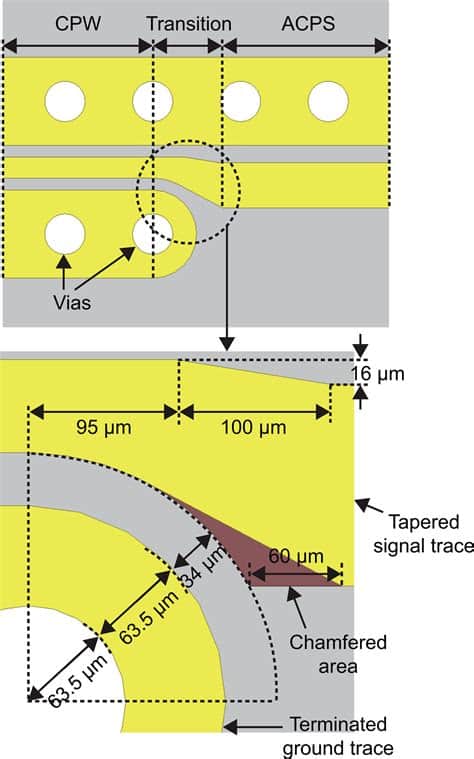
Discontinuities in the CPW, such as bends, T-junctions, and crosses, can cause reflections and radiation losses. To minimize these effects, the discontinuities should be designed with smooth transitions and optimized geometries. Chamfered or mitered bends, for example, can help reduce reflections compared to right-angle bends.
Transitions between the CPW and other transmission lines, such as microstrip or stripline, should also be carefully designed to maintain impedance matching and minimize losses. Tapered transitions or radial stubs can be used to achieve a smooth transition between different Transmission Line Types.
Simulation and Optimization
Before fabricating a CPW, it is essential to simulate its performance using electromagnetic simulation software, such as Ansys HFSS, Keysight ADS, or CST Studio Suite. These tools allow designers to analyze the CPW’s impedance, loss, and dispersion characteristics and optimize its geometry for the desired performance.
Simulation also helps identify potential issues, such as unwanted modes or resonances, and allows for the incorporation of manufacturing tolerances into the design.

Coplanar Waveguide Applications
Coplanar waveguides find applications in various high-frequency and microwave systems, such as:
- Microwave integrated circuits (MICs) and monolithic microwave integrated circuits (MMICs)
- Radio frequency (RF) and microwave filters
- Impedance matching networks
- Power dividers and combiners
- Antenna feed networks
- High-speed digital interconnects
- Microwave sensors and transducers
In these applications, CPWs offer the advantages of low dispersion, easy integration, and flexible impedance control, making them a popular choice for high-frequency circuit design.
Frequently Asked Questions (FAQ)
-
Q: What is the difference between a coplanar waveguide and a microstrip line?
A: A coplanar waveguide has the center conductor and ground planes on the same plane, while a microstrip line has the conductor on top of the substrate and the ground plane on the bottom. CPWs offer lower dispersion and easier integration with components, while microstrip lines are simpler to fabricate and have a smaller footprint. -
Q: Can I use a coplanar waveguide calculator for any frequency range?
A: Coplanar waveguide calculators are typically designed for microwave frequencies (1 GHz and above). At lower frequencies, the dimensions of the CPW may become impractically large, and other transmission line types, such as stripline or coaxial cable, may be more suitable. -
Q: How do I choose the right substrate material for my coplanar waveguide?
A: The choice of substrate material depends on the specific application requirements, such as the operating frequency, loss tolerance, and environmental conditions. Factors to consider include the dielectric constant, loss tangent, thermal stability, and mechanical properties of the substrate. Consulting the manufacturer’s data sheets and application notes can help in selecting the appropriate substrate material. -
Q: What is the effect of increasing the gap width in a coplanar waveguide?
A: Increasing the gap width between the center conductor and the ground planes will increase the characteristic impedance of the CPW. This is because the wider gap reduces the capacitance between the conductor and the ground planes, which in turn increases the impedance. However, increasing the gap width also increases the radiation loss and the dispersion of the CPW. -
Q: How do I connect a coplanar waveguide to other components in my microwave circuit?
A: Connecting a CPW to other components can be done using various techniques, such as wire bonding, flip-chip bonding, or soldering. The choice of the connection method depends on the frequency of operation, the power handling requirements, and the packaging constraints. Proper impedance matching and transition design are crucial to minimize reflections and losses at the interconnects.
Conclusion
Coplanar waveguides are essential components in high-frequency and microwave circuits, offering low dispersion, easy integration, and flexible impedance control. Understanding the principles of CPW design and using a coplanar waveguide calculator can help engineers and researchers create optimized CPWs for their specific applications.
When designing a CPW, it is important to consider factors such as substrate selection, conductor material and thickness, ground plane design, and discontinuity management. Simulation and optimization tools are valuable assets in the design process, helping to identify potential issues and improve performance.
As the demand for high-frequency and high-speed systems continues to grow, coplanar waveguides will remain a key enabling technology for various applications, from microwave integrated circuits to high-speed digital interconnects.
No responses yet