What are Class C Amplifiers?
Class C amplifiers are a type of power amplifier that operates the active device in a highly nonlinear mode, conducting for less than half of the input signal cycle. This operation mode results in high efficiency, as the active device is turned off for a significant portion of the input signal cycle, minimizing power dissipation. However, this high efficiency comes at the cost of increased distortion in the amplified signal.
How Class C Amplifiers Work
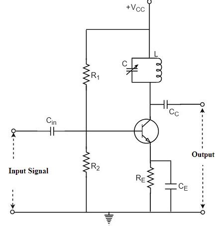
In a Class C amplifier, the active device (transistor or vacuum tube) is biased so that it conducts only during a small portion of the positive half-cycle of the input signal. The conduction angle, which is the portion of the input signal cycle during which the active device conducts, is typically less than 180 degrees (50% of the cycle). This means that the active device is turned off for more than half of the input signal cycle.
When the active device is conducting, it operates in a highly nonlinear region, causing the output signal to be distorted. This distortion is primarily composed of odd-order harmonics of the input signal frequency. To remove these harmonics and recover the fundamental frequency, a tuned LC circuit (tank circuit) is used at the output of the amplifier. The tank circuit is designed to resonate at the desired output frequency, filtering out the unwanted harmonics.
Conduction Angle and Efficiency
The conduction angle is a crucial parameter in Class C amplifiers, as it determines the trade-off between efficiency and distortion. A smaller conduction angle results in higher efficiency but also higher distortion. Conversely, a larger conduction angle reduces distortion but also decreases efficiency.
The theoretical maximum efficiency of a Class C amplifier is 100%, which occurs when the conduction angle approaches zero. However, in practice, the efficiency is limited by various factors, such as the saturation voltage of the active device, the losses in the tank circuit, and the power consumed by the biasing network.
Typical conduction angles for Class C amplifiers range from 90 to 150 degrees, resulting in efficiencies between 70% and 85%. In comparison, Class A amplifiers have a theoretical maximum efficiency of 50%, while Class B amplifiers can achieve a maximum efficiency of about 78.5%.
Applications of Class C Amplifiers
Class C amplifiers are primarily used in applications where high efficiency is crucial, and the distortion introduced by the amplifier can be tolerated or filtered out. Some of the main applications include:
1. RF Power Amplifiers
Class C amplifiers are widely used in radio frequency (RF) power amplifiers, such as those found in wireless communication systems, radar transmitters, and industrial RF heating equipment. In these applications, the high efficiency of Class C amplifiers is essential for minimizing power consumption and reducing heat generation.
2. Switched-Mode Power Supplies (SMPS)
Class C amplifiers are sometimes used in the output stages of switched-mode power supplies, particularly in resonant converter topologies like the Class E and Class F amplifiers. These topologies leverage the high efficiency of Class C operation to achieve compact and efficient power supplies.
3. Magnetic Resonance Imaging (MRI) Systems
MRI systems require high-power RF amplifiers to generate the strong magnetic fields needed for imaging. Class C amplifiers are often employed in these systems due to their high efficiency, which helps to minimize the size and cooling requirements of the amplifiers.

Advantages and Limitations of Class C Amplifiers
Advantages
-
High efficiency: Class C amplifiers offer the highest efficiency among the basic amplifier classes (A, B, and C), with practical efficiencies ranging from 70% to 85%.
-
Reduced heat generation: The high efficiency of Class C amplifiers results in less power dissipation and heat generation, which simplifies the thermal management of the amplifier and reduces the size of the required heat sinks.
-
Compact size: Due to their high efficiency and reduced heat generation, Class C amplifiers can be designed with smaller components and a more compact layout compared to other amplifier classes with similar output power.
Limitations
-
High distortion: Class C amplifiers introduce significant distortion in the amplified signal due to the highly nonlinear operation of the active device. This distortion must be filtered out using a tuned output circuit, which limits the bandwidth of the amplifier.
-
Narrow bandwidth: The tuned output circuit required to filter out the harmonics generated by the Class C amplifier restricts the bandwidth of the amplifier. This makes Class C amplifiers unsuitable for applications that require a wide range of frequencies to be amplified.
-
Poor linearity: Class C amplifiers have poor linearity due to the highly nonlinear operation of the active device. This means that the output signal does not vary linearly with the input signal, which can be problematic in applications that require a high degree of signal fidelity.
-
Requires a tuned load: Class C amplifiers require a tuned load (tank circuit) to filter out the harmonics and recover the fundamental frequency. This tuned load must be carefully designed and matched to the amplifier’s output characteristics, which can be challenging in practice.

Designing Class C Amplifiers
Designing a Class C amplifier involves several key considerations, including the choice of active device, biasing network, and output tuning circuit. Here are some essential steps in the design process:
1. Active Device Selection
The first step in designing a Class C amplifier is to select an appropriate active device, such as a transistor or vacuum tube. The device should have sufficient power handling capability, gain, and frequency response for the intended application. Important parameters to consider include the maximum collector or drain voltage, maximum collector or drain current, and transition frequency (fT).
2. Biasing Network Design
The biasing network is responsible for setting the operating point of the active device to achieve Class C operation. This involves applying a negative bias voltage to the base or gate of the device, so that it conducts only during a small portion of the input signal cycle. The biasing network must be designed to provide stable and accurate bias voltage over the desired operating range of the amplifier.
3. Output Tuning Circuit Design
The output tuning circuit, also known as the tank circuit, is a parallel LC resonant circuit that is tuned to the desired output frequency. Its purpose is to filter out the harmonics generated by the Class C amplifier and recover the fundamental frequency. The tank circuit must be designed to have a high Q factor (quality factor) to effectively suppress the harmonics and minimize losses.
The values of the inductor (L) and capacitor (C) in the tank circuit are determined by the desired resonant frequency (f0) and the load impedance (RL) presented to the amplifier. The following equations can be used to calculate the values of L and C:
L = RL / (2 * π * f0 * QL)
C = 1 / (2 * π * f0)^2 * L
where QL is the loaded Q factor of the tank circuit, typically ranging from 3 to 10.
4. Input and Output Matching Networks
To maximize power transfer and minimize reflections, input and output matching networks are often used to match the impedance of the active device to the source and load impedances, respectively. These matching networks can be designed using lumped elements (inductors and capacitors) or distributed elements (transmission lines) depending on the frequency of operation and the required bandwidth.
5. Thermal Management
Due to the high power dissipation in Class C amplifiers, proper thermal management is crucial to ensure reliable operation and prevent damage to the active device. This involves selecting an appropriate heat sink and designing an efficient cooling system to remove the generated heat. Thermal simulation tools can be used to optimize the thermal design and ensure that the active device operates within its safe operating area (SOA).

Class C Amplifier Variants
Several variants of the Class C amplifier have been developed to further improve efficiency or address specific application requirements. Some of these variants include:
Class D Amplifiers
Class D amplifiers, also known as switching amplifiers, use pulse-width modulation (PWM) to convert the input signal into a series of high-frequency pulses. These pulses are then filtered to recover the amplified output signal. Class D amplifiers can achieve efficiencies up to 90% or higher, making them popular in audio and power electronics applications.
Class E Amplifiers
Class E amplifiers are a highly efficient variant of Class C amplifiers that utilize a single transistor and a tuned load network. The load network is designed to shape the voltage and current waveforms across the transistor, minimizing power dissipation and achieving efficiencies up to 95%. Class E amplifiers are commonly used in RF power amplifiers and switched-mode power supplies.
Class F Amplifiers
Class F amplifiers are another variant of Class C amplifiers that employ harmonic tuning to improve efficiency. By presenting a high impedance to the odd harmonics and a low impedance to the even harmonics of the fundamental frequency, Class F amplifiers can achieve efficiencies up to 90%. This is accomplished using a multi-resonant output network that provides the desired harmonic terminations.
FAQ
1. What is the main difference between Class C and Class A amplifiers?
The main difference between Class C and Class A amplifiers lies in their conduction angles and efficiency. Class A amplifiers have a conduction angle of 360 degrees, meaning the active device conducts for the entire input signal cycle, resulting in low distortion but low efficiency (around 50%). On the other hand, Class C amplifiers have a conduction angle less than 180 degrees, conducting for less than half of the input signal cycle, which results in high efficiency (70-85%) but higher distortion.
2. Can Class C amplifiers be used for audio applications?
Class C amplifiers are generally not suitable for audio applications due to their high distortion and narrow bandwidth. The distortion introduced by Class C amplifiers would result in poor audio quality, and the narrow bandwidth would limit the range of audio frequencies that could be amplified. Class AB or Class D amplifiers are more commonly used in audio applications, as they provide a better balance between efficiency and distortion.
3. What is the purpose of the tuned output circuit in a Class C amplifier?
The tuned output circuit, also known as the tank circuit, is a parallel LC resonant circuit used to filter out the harmonics generated by the Class C amplifier and recover the fundamental frequency. The tank circuit is designed to resonate at the desired output frequency, presenting a high impedance to the harmonics and effectively suppressing them, while allowing the fundamental frequency to pass through to the load.
4. How does the conduction angle affect the efficiency and distortion of a Class C amplifier?
The conduction angle is a crucial parameter in Class C amplifiers that determines the trade-off between efficiency and distortion. A smaller conduction angle results in higher efficiency but also higher distortion, as the active device conducts for a shorter portion of the input signal cycle. Conversely, a larger conduction angle reduces distortion but also decreases efficiency, as the active device conducts for a larger portion of the input signal cycle.
5. What are some common applications for Class C amplifiers?
Class C amplifiers are commonly used in applications that require high efficiency and can tolerate the distortion introduced by the amplifier. Some common applications include:
- RF power amplifiers in wireless communication systems, radar transmitters, and industrial RF heating equipment.
- Switched-mode power supplies, particularly in resonant converter topologies like Class E and Class F amplifiers.
- Magnetic Resonance Imaging (MRI) systems, where high-power RF amplifiers are used to generate strong magnetic fields for imaging.
| Amplifier Class | Conduction Angle | Theoretical Max. Efficiency | Practical Efficiency Range | Distortion |
|---|---|---|---|---|
| Class A | 360° | 50% | 20-30% | Low |
| Class B | 180° | 78.5% | 50-65% | Moderate |
| Class C | <180° | 100% | 70-85% | High |
Table 1: Comparison of Class A, B, and C amplifiers in terms of conduction angle, efficiency, and distortion.
| Application | Frequency Range | Typical Output Power | Amplifier Class |
|---|---|---|---|
| Wireless Communications | 100 MHz – 5 GHz | 1 W – 100 W | Class C, E, F |
| Radar Systems | 1 GHz – 40 GHz | 10 W – 1 kW | Class C, E, F |
| Industrial RF Heating | 1 MHz – 100 MHz | 100 W – 10 kW | Class C, E |
| Magnetic Resonance Imaging | 1 MHz – 100 MHz | 1 kW – 30 kW | Class C |
Table 2: Common applications of Class C amplifiers and their typical frequency ranges, output power levels, and amplifier classes used.
In conclusion, Class C amplifiers are a powerful and efficient type of amplifier that find use in a wide range of high-frequency, high-power applications. By understanding their working principles, design considerations, and limitations, engineers can effectively leverage Class C amplifiers to achieve high-performance, energy-efficient systems in fields such as wireless communications, radar, industrial heating, and medical imaging.
No responses yet