What is a Bypass Capacitor?
A bypass capacitor, also known as a decoupling capacitor, is a small capacitor used in electronic circuits to reduce noise and stabilize the power supply voltage. It is connected in parallel with the power supply and ground, close to the integrated circuit (IC) or other components that require a clean and stable power supply.
The primary purpose of a bypass capacitor is to provide a low-impedance path for high-frequency noise, effectively “bypassing” or “short-circuiting” the noise to ground. This helps to prevent the noise from interfering with the proper operation of the circuit components.
Types of Bypass Capacitors
There are several types of capacitors commonly used as bypass capacitors:
- Ceramic capacitors
- Tantalum capacitors
- Electrolytic capacitors
- Film capacitors
Each type has its own characteristics, such as capacitance range, voltage rating, and frequency response, making them suitable for different applications.
Ceramic Capacitors
Ceramic capacitors are the most commonly used type of bypass capacitor. They are inexpensive, small in size, and have a wide range of capacitance values (typically from 1 pF to 1 μF). Ceramic capacitors also have a good high-frequency response, making them effective at filtering high-frequency noise.
| Characteristic | Value |
|---|---|
| Capacitance range | 1 pF to 1 μF |
| Voltage rating | 6.3 V to 100 V |
| Temperature coefficient | C0G/NP0, X7R, Y5V |
| Package types | 0201, 0402, 0603, 0805, 1206 |
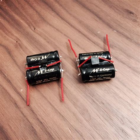
Tantalum Capacitors
Tantalum capacitors offer higher capacitance values than ceramic capacitors for a given size. They are polarized, meaning they have a positive and negative terminal, and they must be connected with the correct polarity to avoid damage. Tantalum capacitors are often used in applications that require higher capacitance values and better stability over temperature.
| Characteristic | Value |
|---|---|
| Capacitance range | 0.1 μF to 1000 μF |
| Voltage rating | 2.5 V to 50 V |
| ESR (Equivalent Series Resistance) | Low |
| Package types | SMD (Surface Mount Device), through-hole |
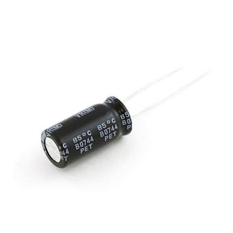
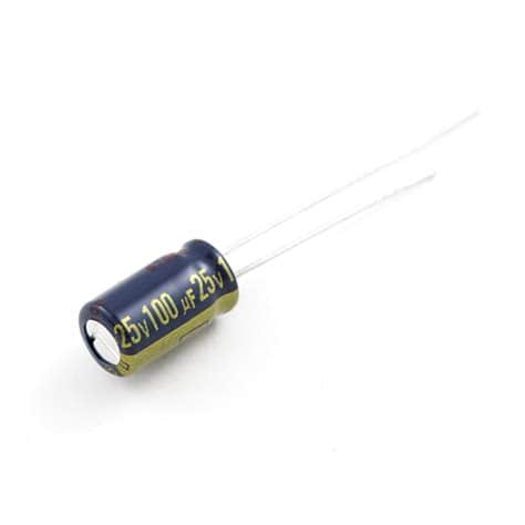
Electrolytic Capacitors
Electrolytic capacitors are polarized capacitors that offer the highest capacitance values among bypass capacitors. They are available in both aluminum and tantalum types. However, they have higher ESR and lower frequency response compared to ceramic and tantalum capacitors. Electrolytic capacitors are often used in Power Supply Filtering applications.
| Characteristic | Value |
|---|---|
| Capacitance range | 1 μF to 10,000 μF |
| Voltage rating | 6.3 V to 450 V |
| ESR (Equivalent Series Resistance) | Moderate to high |
| Package types | Radial, axial, SMD |
Film Capacitors
Film capacitors, such as polyester and polypropylene types, offer low ESR and high stability. They are suitable for applications that require low noise and high precision. However, film capacitors have lower capacitance values compared to electrolytic capacitors and are generally larger in size.
| Characteristic | Value |
|---|---|
| Capacitance range | 1 nF to 10 μF |
| Voltage rating | 50 V to 1000 V |
| ESR (Equivalent Series Resistance) | Low |
| Package types | Radial, axial, SMD |
How to Select the Right Bypass Capacitor
When selecting a bypass capacitor, consider the following factors:
- Capacitance value
- Voltage rating
- Frequency response
- ESR (Equivalent Series Resistance)
- Size and package type
Capacitance Value
The capacitance value of a bypass capacitor should be chosen based on the frequency of the noise to be filtered and the amount of current drawn by the circuit. A general rule of thumb is to use a capacitance value that is at least 10 times larger than the expected noise frequency. For example, if the noise frequency is 100 MHz, use a capacitor with a value of at least 1 nF (1000 pF).
Voltage Rating
The voltage rating of the bypass capacitor should be higher than the maximum voltage expected in the circuit. It is recommended to choose a capacitor with a voltage rating at least 50% higher than the power supply voltage to provide a safety margin.
Frequency Response
The frequency response of the bypass capacitor should be suitable for the frequency range of the noise to be filtered. Ceramic capacitors generally have a good high-frequency response, while electrolytic capacitors are better suited for lower frequencies.
ESR (Equivalent Series Resistance)
The ESR of a bypass capacitor should be as low as possible to ensure effective noise filtering. A high ESR can limit the capacitor’s ability to suppress high-frequency noise. Ceramic and film capacitors typically have lower ESR values compared to electrolytic capacitors.
Size and Package Type
The size and package type of the bypass capacitor should be chosen based on the available space on the printed circuit board (PCB) and the required mounting method. Surface mount devices (SMD) are commonly used in modern electronics due to their small size and ease of automated assembly.
Placement and Layout Considerations
The placement and layout of bypass capacitors on a PCB are critical for their effectiveness in noise reduction. Follow these guidelines for optimal performance:
-
Place the bypass capacitor as close as possible to the power and ground pins of the IC or component being bypassed. Minimizing the distance between the capacitor and the IC reduces the inductance of the connection, improving the high-frequency performance.
-
Use wide and short traces to connect the bypass capacitor to the power and ground planes. This reduces the inductance and resistance of the connection, enhancing the capacitor’s effectiveness.
-
Use multiple bypass capacitors in parallel to achieve a lower effective ESR and to cover a wider frequency range. A common practice is to use a larger capacitor (e.g., 10 μF) for low-frequency bypassing and a smaller capacitor (e.g., 0.1 μF) for high-frequency bypassing.
-
Avoid placing bypass capacitors near high-frequency noise sources, such as switching regulators or digital clock lines, to prevent coupling of noise into the capacitor.
-
Consider using power and ground planes in the PCB design to provide a low-impedance path for the bypass capacitors. This helps to distribute the bypassing effect evenly across the board.

Frequently Asked Questions (FAQ)
-
What happens if I don’t use a bypass capacitor?
Without a bypass capacitor, high-frequency noise can couple into the power supply lines and cause interference with the proper operation of the circuit components. This can lead to issues such as signal distortion, reduced performance, and even device malfunction. -
Can I use a single large capacitor instead of multiple smaller ones?
While a single large capacitor can provide low-frequency bypassing, it may not be as effective at high frequencies due to its higher ESR and inductance. Using multiple smaller capacitors in parallel allows for better high-frequency performance and a lower overall ESR. -
How do I determine the optimal capacitance value for my application?
The optimal capacitance value depends on factors such as the frequency of the noise to be filtered, the amount of current drawn by the circuit, and the available space on the PCB. As a general guideline, use a capacitance value that is at least 10 times larger than the expected noise frequency, and consider using multiple capacitors in parallel to cover a wider frequency range. -
Can I use a polarized capacitor, such as an electrolytic or tantalum capacitor, for bypassing?
Yes, polarized capacitors can be used for bypassing, especially when higher capacitance values are required. However, it is essential to ensure that the capacitor is connected with the correct polarity and that the voltage rating is appropriate for the application. Polarized capacitors also have higher ESR and lower frequency response compared to non-polarized capacitors like ceramic and film types. -
What is the difference between a bypass capacitor and a decoupling capacitor?
The terms “bypass capacitor” and “decoupling capacitor” are often used interchangeably. Both refer to capacitors used to reduce noise and stabilize the power supply voltage in electronic circuits. However, some engineers may use “decoupling capacitor” to specifically refer to capacitors used to isolate one part of a circuit from another, while “bypass capacitor” may be used more generally for capacitors that filter noise from the power supply.
In conclusion, bypass capacitors are essential components in electronic circuits for reducing noise and ensuring stable power supply voltage. By understanding the types of bypass capacitors, selection criteria, and proper placement and layout techniques, designers can effectively implement these components to improve circuit performance and reliability.
No responses yet