Introduction to Buzzer Circuits
A buzzer circuit is an electronic device that produces an audible sound when activated. Buzzer circuits are widely used in various applications, such as alarms, timers, and user interfaces. In this article, we will explore the basics of buzzer circuits, how to create a simple buzzer circuit, and ways to enhance the design for improved functionality.
What is a Buzzer?
A buzzer is an audio signaling device that converts electrical energy into sound. There are two main types of buzzers:
- Piezoelectric Buzzers: These buzzers use a piezoelectric element that vibrates when an electric current is applied, producing sound.
- Electromagnetic Buzzers: These buzzers consist of a coil and a diaphragm. When current flows through the coil, it creates a magnetic field that attracts and repels the diaphragm, generating sound.
Applications of Buzzer Circuits
Buzzer circuits find applications in various fields, including:
- Alarms and security systems
- Timers and reminders
- User interfaces and feedback systems
- Automotive and industrial equipment
Basic Components of a Buzzer Circuit
A simple buzzer circuit consists of the following components:
- Power Source: A battery or power supply that provides the necessary voltage and current to drive the buzzer.
- Buzzer: The audio signaling device that produces the sound.
- Switch: A device that controls the flow of current in the circuit, turning the buzzer on or off.
- Resistor (optional): A component that limits the current flowing through the buzzer to prevent damage.
Choosing the Right Components
When selecting components for your buzzer circuit, consider the following factors:
- Voltage Rating: Ensure that the buzzer and other components are compatible with the power source voltage.
- Current Rating: Choose a buzzer and resistor that can handle the required current without overheating or damage.
- Frequency and Sound Level: Select a buzzer with the desired frequency and sound level for your application.

Creating a Simple Buzzer Circuit
Follow these steps to create a basic buzzer circuit:
- Connect the positive terminal of the power source to one of the buzzer’s leads.
- Connect the other buzzer lead to one end of the switch.
- Connect the other end of the switch to the negative terminal of the power source.
- (Optional) If using a resistor, connect it in series with the buzzer to limit the current.
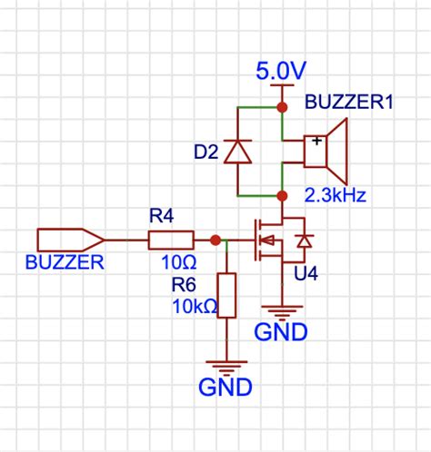
Here’s a simple schematic diagram of a buzzer circuit:
    Power Source
        |
        |
     Buzzer
        |
        |
      Switch
        |
        |
     Ground
Testing the Circuit
Once you have assembled the buzzer circuit, test it by following these steps:
- Ensure that all connections are secure and properly made.
- Turn on the power source.
- Activate the switch to close the circuit and trigger the buzzer.
- If the buzzer does not sound, double-check the connections and component polarities.

Enhancing the Buzzer Circuit Design
To improve the functionality and versatility of your buzzer circuit, consider the following enhancements:
Adding a Microcontroller
Incorporating a microcontroller, such as an Arduino or Raspberry Pi, into your buzzer circuit allows for more advanced control and customization. With a microcontroller, you can:
- Generate different tones and patterns
- Control the buzzer’s duration and intervals
- Integrate sensors and other inputs to trigger the buzzer
Implementing a Timer
By adding a Timer Circuit, you can control the duration of the buzzer’s activation. This is particularly useful for applications that require timed alerts or notifications. A simple timer circuit can be created using a 555 timer IC and a few additional components.
Adjusting the Sound Level
To change the buzzer’s sound level, you can:
- Use a potentiometer in series with the buzzer to adjust the current and, consequently, the sound level.
- Implement a digital volume control using a microcontroller and Pulse-Width Modulation (PWM).
Creating a Melody
By carefully controlling the buzzer’s activation and frequency, you can create simple melodies or tunes. This can be achieved by:
- Using a microcontroller to generate specific frequencies and durations.
- Storing melody data in an array and playing it back through the buzzer.

Troubleshooting Common Issues
If you encounter problems with your buzzer circuit, consider the following troubleshooting tips:
- Check the power source voltage and ensure it matches the buzzer’s specifications.
- Verify that all connections are secure and properly made.
- Ensure the buzzer and other components are properly polarized (if applicable).
- Check for any short circuits or open connections in the circuit.
- Test the buzzer and switch independently to isolate the issue.
Frequently Asked Questions (FAQ)
-
Q: Can I use any type of buzzer in my circuit?
A: While most buzzers can be used interchangeably, it’s essential to ensure that the buzzer’s voltage and current ratings are compatible with your power source and circuit design. -
Q: How do I calculate the appropriate resistor value for my buzzer circuit?
A: To determine the resistor value, use Ohm’s law: R = (V_supply – V_buzzer) / I_buzzer, where R is the resistor value, V_supply is the power source voltage, V_buzzer is the buzzer’s operating voltage, and I_buzzer is the buzzer’s rated current. -
Q: Can I control multiple buzzers with a single microcontroller?
A: Yes, you can control multiple buzzers with a single microcontroller by assigning each buzzer to a different GPIO pin and controlling them independently. -
Q: How can I make my buzzer circuit more energy-efficient?
A: To improve energy efficiency, use a low-power buzzer, minimize the buzzer’s active time, and consider implementing sleep modes or power-saving techniques when the buzzer is not in use. -
Q: Are there any safety considerations when working with buzzer circuits?
A: Always ensure that you are working with safe voltage and current levels. Be cautious when handling circuits connected to high-voltage power sources, and avoid touching exposed wire or terminals to prevent electric shock.
Conclusion
Buzzer circuits are simple yet versatile electronic devices that find applications in various fields. By understanding the basic components and principles of buzzer circuits, you can create your own designs and enhance them with additional features and functionalities. Whether you are building an alarm system, a user interface, or an educational project, buzzer circuits provide an easy and effective way to add audio feedback to your electronic projects.
Remember to choose the right components, follow the circuit diagram, and test your design thoroughly. With practice and experimentation, you can create increasingly complex and sophisticated buzzer circuits that meet your specific needs and requirements.
No responses yet