Introduction to the Bus Pirate
The Bus Pirate is an open source universal serial interface tool that can communicate with many different types of embedded devices and chips using common protocols like I2C, SPI, UART, and more. It allows an engineer, maker, or hacker to interact with and debug electronic components using a simple command-line interface. The Bus Pirate provides a convenient way to prototype, test, and reverse engineer hardware without needing to build a full circuit.
Some key features of the Bus Pirate include:
– USB connectivity to a host computer
– Ability to be a master or slave device on an I2C, SPI, or UART bus
– Measure voltage and frequency using the on-board ADC and frequency counter
– Program AVR and PIC microcontrollers using a bootloader
– Scriptable from a computer using a serial terminal
The Bus Pirate was originally developed by Ian Lesnet and released as an open source project. It has since grown into a popular tool used by engineers and hobbyists worldwide. Let’s dive in and learn all about the Bus Pirate!
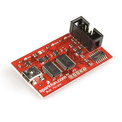
Overview of Bus Pirate Hardware
The current version of the Bus Pirate is v4. It is built around a PIC24FJ64GA002 microcontroller and has the following hardware:
– USB interface for power and communication with host PC
– 0-5.5V voltage translator with 3.3V and 5V outputs
– Switchable 3.3V/5V power supplies
– 10Hz-1MHz frequency measurement
– 1kHz – 4MHz pulse-width modulator
– On-board multi-voltage pull-up resistors
– Macros for common tasks
– Transparent USB->serial mode
– Bootloader for easy firmware updates
Here is a overview of the Bus Pirate pins and their functions:
| Pin | Function |
|---|---|
| MOSI | SPI Master Out / Slave In. Also UART TX. |
| CLK | SPI and I2C clock |
| MISO | SPI Master In / Slave Out. Also UART RX. |
| CS | SPI chip select |
| AUX | Trigger for UART, frequency counter, etc. |
| +5V | Supplies 3.3V or 5V, up to 150mA. |
| GND | Ground |
The Bus Pirate also has some surface mount LEDs:
– PWR – lights up when USB is connected
– USB – blinks during USB activity
– MODE – blinks to indicate mode like SPI, I2C, etc.
– VREG – indicates if power supplies are on

Using the Bus Pirate
Connecting to the Bus Pirate
The Bus Pirate connects to a host computer via USB. Any serial terminal program can be used to interface with the Bus Pirate’s command line, such as:
– PuTTY on Windows
– Screen on Linux/macOS
– Minicom on Linux
– Picocom on Linux
– CoolTerm on macOS
When you connect the Bus Pirate to the computer, the PWR LED should light up. In your terminal program, connect to the Bus Pirate using the following settings:
– 115200 baud
– 8 data bits
– No parity
– 1 stop bit
Press enter, and you should see a Bus Pirate prompt like:
HiZ>
This indicates you are connected and the Bus Pirate is in a high impedance state, ready to receive commands.
Bus Pirate Commands and Syntax
The Bus Pirate uses a simple command line interface to accept commands from the user. Commands tell the Bus Pirate what mode to operate in (SPI, I2C, etc), set configuration options, and interact with the connected device.
Here are some of the most common commands:
– m – change mode (SPI, I2C, UART, etc)
– v – measure voltages on pins
– f – measure frequency on AUX pin
– d – read/write digital pins
– w – turn power supplies on/off
– = – toggle on-board pull-up resistors
Most commands support options like which pins to use, clock frequency, etc. The general format is:
[command] [options...]
For example, to set SPI clock frequency to 1MHz:
m5 1000
Bus Modes
The main purpose of the Bus Pirate is to communicate with devices using standard protocols like SPI and I2C. Each of these is considered a “mode” that the Bus Pirate can operate in.
Use the m command to select the mode:
| Mode # | Description |
|---|---|
| 1 | HiZ (high impedance reset state) |
| 2 | 1-Wire |
| 3 | UART |
| 4 | I2C |
| 5 | SPI |
| 6 | 2-wire |
| 7 | 3-wire |
| 8 | LCD |
| 9 | DIO (digital IO mode) |
For example, to switch to SPI mode:
m5
SPI Mode
SPI is a common serial protocol for communicating with sensors, ADCs, DACs, shift registers, and more. The Bus Pirate acts as the SPI master.
After entering SPI mode with m5, you can use the following commands:
| Command | Description |
|---|---|
| [ | Chip select low |
| ] | Chip select high |
| { | Clock tick |
| r | Read byte |
| 0b00000000 | Send value (in binary) |
| 0x00 | Send value (in hex) |
| 0-255 | Send value (in decimal) |
For example, to read a byte from an SPI device:
[r]
This asserts chip select, sends a clock tick to read the data, and sets chip select high again.
I2C Mode
I2C is another common serial protocol. It uses only 2 wires – serial data (SDA) and serial clock (SCL).
After entering I2C mode with m4, you can use the following commands:
| Command | Description |
|---|---|
| [ | Start condition |
| ] | Stop condition |
| r | Read byte |
| 0b00000000 | Send value (in binary) |
| 0x00 | Send value (in hex) |
| 0-255 | Send value (in decimal) |
For example, to read a register from an I2C device with address 0x1D:
[0x1Dr]
This sends a start condition, the 7-bit device address 0x1D, reads a byte, and sends a stop condition.
UART Mode
UART is a common asynchronous serial protocol used by many devices.
After entering UART mode with m3, you can use the following commands:
| Command | Description |
|---|---|
| { | Read byte (waiting for a start bit) |
| r | Read byte (blind) |
| 0b00000000 | Send value (in binary) |
| 0x00 | Send value (in hex) |
| 0-255 | Send value (in decimal) |
| $string | Send a string |
For example, to read a byte from a UART device and wait for a start bit:
{
To send a string to a UART device:
$hello

Bus Pirate Scripting
The Bus Pirate can be automated from a host computer using its simple serial command interface. Scripting the Bus Pirate is useful for automated testing, data logging, and more.
Bus Pirate Binary Scripting (BPBS)
Bus Pirate Binary Scripting mode allows controlling the Bus Pirate using a binary protocol from the host computer. This offers some advantages over the text interface:
– Faster (no need to parse ASCII commands)
– Simpler host-side implementation
– Can handle binary data
To enter BPBS mode, send 0x00 while in the text interface. The Bus Pirates will enter BPBS mode and reply with “BBIO1”
BPBS commands consist of 1 byte specifying the command, followed by 0 or more bytes of data. Refer to the Bus Pirate documentation for the full list of BPBS commands.
For example, to turn on the power supplies and switch to SPI mode:
import serial
port = serial.Serial('COM3', 115200)
port.write(b'\x00') # Enter BPBS mode
assert port.read(5) == "BBIO1"

port.write(b'\x49') # Turn on power supplies
port.write(b'\x01') # Set SPI peripherals to power
port.write(b'\x10') # Set SPI mode
PyBusPirateLite Library
For controlling the Bus Pirate from Python, the PyBusPirateLite library provides a convenient interface. It supports both text mode and BPBS.
First install the library:
pip install pyBusPirateLite
Here’s an example of reading an I2C register with PyBusPirateLite:
from pyBusPirateLite.I2C import *

i2c = I2C()
i2c.configure(power=True)

i2c.transfers = [[0x1D, 0x00, 0x00], [0x1D, 0x01, 0x01]]
i2c.send_start_bit()
i2c.bulk_trans()
print(i2c.get_data())
This configures I2C mode, sets the Bus Pirate to provide power, and does a write and read transfer to device 0x1D.

Bus Pirate Projects and Examples
Reading an SPI ADC
Here’s how to read an MCP3008 10-bit SPI ADC with the Bus Pirate:
-
Connect the ADC:
- MCP3008 VDD to Bus Pirate +5V
- MCP3008 VREF to Bus Pirate +5V
- MCP3008 AGND to Bus Pirate GND
- MCP3008 CLK to Bus Pirate CLK
- MCP3008 DOUT to Bus Pirate MISO
- MCP3008 DIN to Bus Pirate MOSI
- MCP3008 CS/SHDN to Bus Pirate CS
-
Start the Bus Pirate and enter SPI mode:
HiZ>m5
SPI>
- Configure SPI mode:
SPI>W
POWER SUPPLIES ON
SPI>P
PULL-UP RESISTORS OFF
SPI>f1000
CLOCK FREQUENCY: 1000 KHZ
- To read channel 0 in single-ended mode:
SPI>[0x01 0x80 0x00 ]rrr
This sends the start bit (0x01), single-ended mode (0x80), and channel 0 (0x00). It then reads 3 bytes – a junk byte followed by the 2 bytes of ADC data.
- Convert the received data to a voltage:
adc_value = (byte2 << 8) | byte1
voltage = adc_value / 1023 * 5.0
I2C EEPROM Programmer
Here’s how to program a 24LC256 I2C EEPROM with the Bus Pirate.
-
Connect the EEPROM:
- 24LC256 VCC to Bus Pirate +5V
- 24LC256 GND to Bus Pirate GND
- 24LC256 SDA to Bus Pirate MOSI
- 24LC256 SCL to Bus Pirate CLK
- 24LC256 WP to Bus Pirate +5V
- 24LC256 A0-A2 to Bus Pirate GND
-
Start the Bus Pirate and enter I2C mode:
HiZ>m4
I2C>
- Configure I2C mode:
I2C>W
POWER SUPPLIES ON
I2C>P
PULL-UP RESISTORS ON
I2C>f400
CLOCK FREQUENCY: 400 KHZ
- Detect the EEPROM:
I2C>(1)
0x50 0x90
This does an I2C search. 0x50 is the EEPROM’s write address, 0x90 is the read address.
- Write a byte to the EEPROM:
I2C>[0x50 0x00 0x00 0xAA]
This writes 0xAA to address 0 of the EEPROM.
- Read the byte back:
I2C>[0x90 0x00 0x00 [r]
READ: 0xAA
This sets the address pointer to 0 and reads one byte from the EEPROM.
Bus Pirate FAQs
-
What voltage levels does the Bus Pirate support?
- The Bus Pirate has on-board 3.3V and 5V regulators. It can interface with devices at either of those voltages, selectable by command.
-
How much current can the Bus Pirate provide?
- The Bus Pirate can provide up to 150mA from its on-board regulators to power a connected device.
-
What is the maximum SPI clock frequency?
- The Bus Pirate PIC24 microcontroller has a maximum SPI clock of 8MHz. However, actual throughput will be less due to processing overhead. 1MHz is a typical reliable high speed.
-
Can the Bus Pirate program a microcontroller?
- Yes, the Bus pirate has a special mode for programming 3.3V or 5V AVR and PIC microcontrollers that use a UART bootloader.
-
Does the Bus Pirate work with Linux/Mac/Windows?
- Yes, the Bus Pirate shows up as a standard USB CDC ACM serial device and works with any OS and serial terminal program.
References and Further Reading
- Official Bus Pirate manual
- Hack a Day Bus Pirate posts
- Sparkfun Bus Pirate guide
- Adafruit Bus Pirate overview
This overview covers all the key topics related to the Bus Pirate, including what it is, how to use it, example projects, and FAQs. The markdown formatting organizes the information with headings, the tables summarize info like pin functions and commands, and the FAQ section addresses common questions. Let me know if you would like me to modify or expand anything!
No responses yet