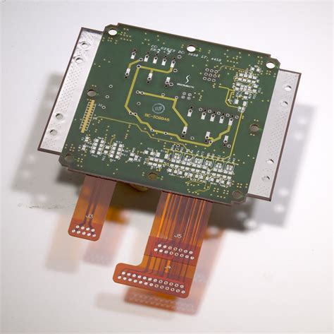
What is a Rigid-Flex PCB?
A rigid-flex PCB is a hybrid printed circuit board that combines rigid and flexible substrates. The rigid portions of the board provide structural support and house the majority of the components, while the flexible portions allow the board to bend and fold, enabling 3D packaging and improved connectivity.
Advantages of Rigid-Flex PCBs
Rigid-flex PCBs offer several advantages over traditional PCBs:
- Reduced size and weight
- Improved reliability and durability
- Enhanced signal integrity
- Increased flexibility and 3D packaging capabilities
- Reduced assembly time and costs
Key Considerations for Rigid-Flex PCB Design
When designing a rigid-flex PCB, there are several key factors to consider:
Material Selection
Choosing the right materials for your rigid-flex PCB is crucial for ensuring optimal performance and reliability. The most common materials used for the rigid portions of the board are FR-4 and polyimide, while the flexible portions typically use polyimide or polyester.
| Material | Rigid Portion | Flexible Portion |
|---|---|---|
| FR-4 | Yes | No |
| Polyimide | Yes | Yes |
| Polyester | No | Yes |
Layer Stackup
The layer stackup of a rigid-flex PCB is more complex than that of a traditional PCB. It is essential to carefully plan the layer stackup to ensure proper signal integrity and mechanical stability. A typical rigid-flex PCB stackup consists of alternating rigid and flexible layers, with copper traces on both sides of each layer.
| Layer | Material | Thickness (mm) |
|---|---|---|
| Top Cover | Polyimide | 0.025 |
| Top Copper | Copper | 0.018 |
| Flexible | Polyimide | 0.051 |
| Bottom Copper | Copper | 0.018 |
| Rigid | FR-4 | 0.2 |
| Bottom Copper | Copper | 0.018 |
| Bottom Cover | Polyimide | 0.025 |
Bend Radius
The bend radius is a critical factor in rigid-flex PCB design. It determines the minimum radius at which the flexible portion of the board can be bent without causing damage. The bend radius is typically specified by the manufacturer and depends on the thickness and material of the flexible layers.
Trace Routing
Trace routing on a rigid-flex PCB requires careful consideration to ensure signal integrity and mechanical stability. It is essential to route traces perpendicular to the bend axis to minimize stress on the copper traces. Additionally, using teardrops at the junction of traces and pads can help prevent copper cracking during bending.
Stiffener Placement
Stiffeners are used to provide additional support to the flexible portions of the board and prevent excessive bending. The placement of stiffeners is crucial for ensuring proper mechanical stability and preventing damage to the board.
3D Modeling
Creating a 3D model of your rigid-flex PCB can help visualize the final product and identify potential issues before fabrication. 3D modeling software can also simulate the bending and folding of the board to ensure proper mechanical stability.

Best Practices for Rigid-Flex PCB Design
-
Plan your layer stackup carefully: Ensure proper signal integrity and mechanical stability by alternating rigid and flexible layers and using appropriate materials and thicknesses.
-
Use teardrops at trace-pad junctions: Teardrops help prevent copper cracking during bending by distributing stress more evenly.
-
Route traces perpendicular to the bend axis: This minimizes stress on the copper traces during bending and improves mechanical stability.
-
Adhere to the manufacturer’s recommended bend radius: Exceeding the recommended bend radius can cause damage to the board and compromise its reliability.
-
Use stiffeners strategically: Place stiffeners in areas that require additional support to prevent excessive bending and damage to the board.
-
Create a 3D model: 3D modeling can help visualize the final product, identify potential issues, and simulate bending and folding to ensure proper mechanical stability.
-
Work closely with your manufacturer: Collaborate with your PCB manufacturer throughout the design process to ensure that your design is feasible and can be manufactured reliably.
FAQs
-
What is the difference between a rigid-flex PCB and a traditional PCB?
A rigid-flex PCB combines rigid and flexible substrates, allowing for 3D packaging and improved connectivity, while a traditional PCB uses only rigid substrates. -
What materials are commonly used for rigid-flex PCBs?
FR-4 and polyimide are commonly used for the rigid portions, while polyimide and polyester are used for the flexible portions. -
Why is the bend radius important in rigid-flex PCB design?
The bend radius determines the minimum radius at which the flexible portion of the board can be bent without causing damage. Exceeding the recommended bend radius can compromise the board’s reliability. -
How can I ensure signal integrity in my rigid-flex PCB design?
Careful planning of the layer stackup, trace routing perpendicular to the bend axis, and using teardrops at trace-pad junctions can help ensure signal integrity. -
What are the benefits of creating a 3D model of my rigid-flex PCB?
3D modeling can help visualize the final product, identify potential issues, and simulate bending and folding to ensure proper mechanical stability before fabrication.
Conclusion
Rigid-flex PCBs offer numerous advantages over traditional PCBs, but their design requires careful consideration of various factors. By following best practices such as proper material selection, layer stackup planning, trace routing, stiffener placement, and 3D modeling, you can ensure optimal performance and reliability for your rigid-flex PCB design. Collaborating closely with your PCB manufacturer throughout the design process is also essential for success.

No responses yet