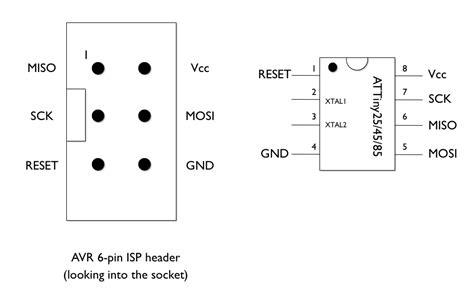
Pin Configuration of Attiny85
The Attiny85 comes in an 8-pin PDIP (Plastic Dual Inline Package) or SOIC (Small Outline Integrated Circuit) package. Here’s a detailed look at the pin configuration:
| Pin Number | Pin Name | Description |
|---|---|---|
| 1 | PB5 | GPIO, ADC Input, Reset |
| 2 | PB3 | GPIO, Analog Comparator Input |
| 3 | PB4 | GPIO, ADC Input |
| 4 | GND | Ground |
| 5 | PB0 | GPIO, PWM Output, MOSI |
| 6 | PB1 | GPIO, PWM Output, MISO |
| 7 | PB2 | GPIO, ADC Input, SCK |
| 8 | VCC | Supply Voltage |
Let’s explore each pin in more detail:
PB5 (Pin 1)
- General Purpose Input/Output (GPIO)
- Analog-to-Digital Converter (ADC) input
- Can be used as an external reset pin
PB3 (Pin 2)
- General Purpose Input/Output (GPIO)
- Analog Comparator positive input
- Can be used for general purpose I/O or analog comparisons
PB4 (Pin 3)
- General Purpose Input/Output (GPIO)
- Analog-to-Digital Converter (ADC) input
- Can be used for general purpose I/O or analog measurements
GND (Pin 4)
- Ground connection
- Provides a reference point for all voltage measurements and connections
PB0 (Pin 5)
- General Purpose Input/Output (GPIO)
- Pulse Width Modulation (PWM) output
- Master Out Slave In (MOSI) for SPI communication
PB1 (Pin 6)
- General Purpose Input/Output (GPIO)
- Pulse Width Modulation (PWM) output
- Master In Slave Out (MISO) for SPI communication
PB2 (Pin 7)
- General Purpose Input/Output (GPIO)
- Analog-to-Digital Converter (ADC) input
- Serial Clock (SCK) for SPI communication
VCC (Pin 8)
- Supply voltage pin
- Connect to a regulated power supply (1.8V to 5.5V)
Key Features of Attiny85
Now that we have a clear understanding of the pin configuration, let’s explore some of the key features of the Attiny85 microcontroller.
Compact Size
The Attiny85 comes in a small 8-pin package, making it ideal for projects with limited space. Its compact size allows for easy integration into wearable devices, IoT sensors, and other space-constrained applications.
Low Power Consumption
Designed for low-power applications, the Attiny85 offers various power-saving modes. It can operate at a wide range of supply voltages, from 1.8V to 5.5V, and consumes minimal current in active and sleep modes. This makes it suitable for battery-powered projects and energy-efficient designs.
Analog-to-Digital Converter (ADC)
The Attiny85 features a 10-bit Analog-to-Digital Converter (ADC) that allows it to measure analog signals and convert them into digital values. With four ADC input channels (PB2, PB3, PB4, PB5), it can handle multiple analog sensors or inputs simultaneously.
Pulse Width Modulation (PWM)
Two pins of the Attiny85 (PB0 and PB1) support Pulse Width Modulation (PWM) output. PWM is commonly used for controlling the brightness of LEDs, driving small motors, or generating analog-like signals. The Attiny85 can generate PWM signals with adjustable duty cycles, allowing for precise control over connected devices.
SPI Communication
The Attiny85 supports Serial Peripheral Interface (SPI) communication, which is a synchronous serial communication protocol widely used for interfacing with external devices such as sensors, displays, or memory chips. With dedicated MOSI (PB0), MISO (PB1), and SCK (PB2) pins, it can easily communicate with SPI-compatible devices.
Programmable Watchdog Timer
The Attiny85 includes a programmable watchdog timer that can be used to detect and recover from software malfunctions or unexpected system behavior. The watchdog timer can be configured to reset the microcontroller if it doesn’t receive a reset signal within a specified time period, ensuring reliable operation.
Interrupt Capability
The Attiny85 supports both internal and external interrupts. Interrupts allow the microcontroller to respond to specific events or conditions without the need for constant polling. This feature enables efficient and responsive system design, as the microcontroller can quickly react to changes in input pins or internal events.
In-System Programming (ISP)
The Attiny85 supports In-System Programming (ISP), which allows you to program the microcontroller without removing it from the target circuit. With an appropriate programmer, such as the AVR ISP or Arduino as ISP, you can easily upload firmware to the Attiny85 through its dedicated programming pins.

Frequently Asked Questions (FAQ)
-
What is the maximum operating frequency of the Attiny85?
The Attiny85 can operate at a maximum frequency of 8 MHz when powered by a 5V supply. However, when running at lower voltages, the maximum frequency is reduced accordingly. For example, at 3.3V, the maximum frequency is 4 MHz. -
Can I use the Attiny85 with the Arduino IDE?
Yes, you can use the Attiny85 with the Arduino IDE. By installing the appropriate board support package and configuring the IDE settings, you can program the Attiny85 using the familiar Arduino programming language and libraries. -
How much Flash memory and SRAM does the Attiny85 have?
The Attiny85 has 8 KB of Flash memory for storing the program code and 512 bytes of SRAM for data storage during program execution. It also features 512 bytes of EEPROM for non-volatile data storage. -
Can I control servo motors with the Attiny85?
Yes, you can control servo motors with the Attiny85 using its PWM output capabilities. By generating appropriate PWM signals on PB0 or PB1 pins, you can control the position of servo motors connected to the microcontroller. -
How can I reduce power consumption in my Attiny85 project?
To reduce power consumption, you can utilize the Attiny85’s power-saving modes, such as the Power-down mode or the Idle mode. Additionally, you can optimize your code to minimize unnecessary operations, use low-power peripherals, and disconnect unused pins or modules to conserve power.

Conclusion
The Attiny85 is a powerful and compact microcontroller that offers a range of features and capabilities in a small package. By understanding its pin configuration and utilizing its analog and digital peripherals, you can create diverse and efficient embedded projects.
From simple LED control to complex sensor integration, the Attiny85 provides a versatile platform for prototyping and developing low-power, space-constrained applications. Its support for SPI communication, PWM output, and analog measurements makes it adaptable to various project requirements.
Whether you are a beginner exploring the world of microcontrollers or an experienced developer seeking a compact solution, the Attiny85 is a valuable tool to have in your arsenal. With its extensive documentation, community support, and compatibility with popular development environments like Arduino, the Attiny85 empowers you to bring your ideas to life.
So, dive into the world of Attiny85 and unlock its potential for your next embedded project. Happy tinkering!

No responses yet