Introduction to the Arduino Pro Micro
The Arduino Pro Micro is a popular microcontroller board designed for projects that demand a small footprint without compromising on features. Measuring just 33mm x 18mm, this board packs a punch with its ATmega32U4 chip, which offers a built-in USB communication capability, eliminating the need for a separate USB-to-serial converter.
Key Features of the Arduino Pro Micro
- Microcontroller: ATmega32U4
- Operating Voltage: 5V
- Input Voltage: 5-12V
- Digital I/O Pins: 12
- PWM Channels: 5
- Analog Input Channels: 4
- Flash Memory: 32KB
- SRAM: 2.5KB
- EEPROM: 1KB
- Clock Speed: 16MHz
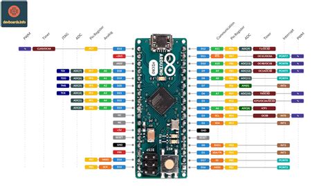
Arduino Pro Micro Pinout Diagram
To better understand the Arduino Pro Micro pinout, let’s take a look at the following diagram:
                        +-----+
          +------------| USB |------------+
          |            +-----+            |
 MISO     |   2             20  GND       | SCK
 RX       |   3             21  RESET     | ▶ TX
          |   4   Vcc       22  GND       |
          |   5   GND       23            |
          |   6             24  A3       ◀|
          |   7             25  A2        |
          |   8   A0◀       26            |
          |   9   A1◀       27            |
          |  10   RST◀      28            |
          |  11             29  SCL      ◀|  INT
 MOSI     |  12   A10       30  SDA      ◀|
          |  13             31            |
          +--------------------------------+

Arduino Pro Micro Pin Functions
Let’s dive into the specific functions of each pin on the Arduino Pro Micro.
Digital I/O Pins
The Arduino Pro Micro has 12 digital input/output pins, labeled 2-13. These pins can be used for digital input (reading a digital sensor) or digital output (controlling an LED or other digital devices). Each pin operates at 5V and can provide or receive a maximum of 40mA.
| Pin | Function |
|---|---|
| 2 | Digital I/O, MISO (SPI) |
| 3 | Digital I/O, RX (UART) |
| 4 | Digital I/O |
| 5 | Digital I/O |
| 6 | Digital I/O |
| 7 | Digital I/O |
| 8 | Digital I/O |
| 9 | Digital I/O |
| 10 | Digital I/O |
| 11 | Digital I/O |
| 12 | Digital I/O, MOSI (SPI) |
| 13 | Digital I/O |
PWM Pins
Among the digital pins, 5 of them (3, 5, 6, 9, and 10) can also function as PWM (Pulse Width Modulation) pins. PWM allows you to simulate analog output by rapidly toggling a digital pin on and off, creating a square wave with a specific duty cycle. This is useful for controlling the brightness of LEDs, the speed of motors, or generating audio signals.
Analog Input Pins
The Arduino Pro Micro has 4 analog input pins, labeled A0-A3. These pins can read analog voltages between 0V and 5V, with a resolution of 10 bits (0-1023). Analog inputs are commonly used for reading sensors that provide a variable voltage output, such as potentiometers, light sensors, or temperature sensors.
| Pin | Function |
|---|---|
| A0 | Analog Input |
| A1 | Analog Input |
| A2 | Analog Input |
| A3 | Analog Input |
Serial Communication Pins
The Arduino Pro Micro supports serial communication through its UART (Universal Asynchronous Receiver/Transmitter) interface. The RX (receive) and TX (transmit) pins are used for serial communication with other devices, such as computers, other microcontrollers, or serial-enabled peripherals.
| Pin | Function |
|---|---|
| 3 | RX (UART) |
| – | TX (USB) |
Note that the TX pin is not physically present on the Pro Micro, as it is connected to the USB interface.
SPI Communication Pins
SPI (Serial Peripheral Interface) is another communication protocol supported by the Arduino Pro Micro. It uses four pins for communication: MISO (Master In Slave Out), MOSI (Master Out Slave In), SCK (Serial Clock), and SS (Slave Select). SPI is commonly used for communicating with sensors, displays, and other peripherals that support high-speed data transfer.
| Pin | Function |
|---|---|
| 2 | MISO (SPI) |
| 12 | MOSI (SPI) |
| – | SCK (SPI) |
| – | SS (SPI) |
The SCK and SS pins are not physically present on the Pro Micro, but they can be assigned to any available digital pin using the SPI library.
I2C Communication Pins
I2C (Inter-Integrated Circuit) is a communication protocol that uses two wires for data transfer: SCL (Serial Clock) and SDA (Serial Data). The Arduino Pro Micro has dedicated I2C pins, making it easy to connect I2C-enabled devices like sensors, displays, and memory modules.
| Pin | Function |
|---|---|
| 29 | SCL (I2C) |
| 30 | SDA (I2C) |
Interrupt Pin
The Arduino Pro Micro has one external interrupt pin, labeled INT on the pinout diagram. This pin can be configured to trigger an interrupt when a specific event occurs, such as a change in the pin’s state or a rising or falling edge. Interrupts are useful for handling time-sensitive tasks or responding to external events without constantly polling the pin’s state.
| Pin | Function |
|---|---|
| – | INT |
The INT pin is not physically present on the Pro Micro, but it can be assigned to any available digital pin using the attachInterrupt() function.

Example Projects using the Arduino Pro Micro
Now that we’ve covered the Arduino Pro Micro pinout and its various functions, let’s explore some practical examples that demonstrate the board’s capabilities.
1. Simple LED Control
This example shows how to control an LED connected to a digital pin on the Arduino Pro Micro.
Required Components:
– Arduino Pro Micro
– LED
– 220Ω resistor
Circuit Diagram:
        Arduino Pro Micro
        +--------------+
        |              |
        |          13  |---|>|---GND
        |              |   LED
        +--------------+
Code:
const int ledPin = 13;

void setup() {
  pinMode(ledPin, OUTPUT);
}

void loop() {
  digitalWrite(ledPin, HIGH);
  delay(1000);
  digitalWrite(ledPin, LOW);
  delay(1000);
}
2. Analog Sensor Reading
This example demonstrates how to read an analog sensor (e.g., a potentiometer) connected to an analog input pin on the Arduino Pro Micro.
Required Components:
– Arduino Pro Micro
– Potentiometer
Circuit Diagram:
        Arduino Pro Micro
        +--------------+
        |              |
   A0   |           A0 |---[  ]---GND
        |              |    POT
        +--------------+
Code:
const int sensorPin = A0;

void setup() {
  Serial.begin(9600);
}

void loop() {
  int sensorValue = analogRead(sensorPin);
  Serial.println(sensorValue);
  delay(100);
}
3. I2C Communication
This example shows how to communicate with an I2C device (e.g., an MPU-6050 accelerometer/gyroscope) using the Arduino Pro Micro.
Required Components:
– Arduino Pro Micro
– MPU-6050 module
Circuit Diagram:
        Arduino Pro Micro              MPU-6050
        +--------------+           +------------+
        |              |           |            |
  SCL   |           29 |-----------|  SCL       |
  SDA   |           30 |-----------|  SDA       |
        |              |           |            |
        +--------------+           +------------+
Code:
#include <Wire.h>

const int MPU_addr=0x68;
int16_t AcX,AcY,AcZ,Tmp,GyX,GyY,GyZ;

void setup() {
  Wire.begin();
  Wire.beginTransmission(MPU_addr);
  Wire.write(0x6B);
  Wire.write(0);
  Wire.endTransmission(true);
  Serial.begin(9600);
}

void loop() {
  Wire.beginTransmission(MPU_addr);
  Wire.write(0x3B);
  Wire.endTransmission(false);
  Wire.requestFrom(MPU_addr,14,true);
  AcX=Wire.read()<<8|Wire.read();
  AcY=Wire.read()<<8|Wire.read();
  AcZ=Wire.read()<<8|Wire.read();
  Tmp=Wire.read()<<8|Wire.read();
  GyX=Wire.read()<<8|Wire.read();
  GyY=Wire.read()<<8|Wire.read();
  GyZ=Wire.read()<<8|Wire.read();

  Serial.print("AcX = "); Serial.print(AcX);
  Serial.print(" | AcY = "); Serial.print(AcY);
  Serial.print(" | AcZ = "); Serial.print(AcZ);
  Serial.print(" | Tmp = "); Serial.print(Tmp/340.00+36.53);
  Serial.print(" | GyX = "); Serial.print(GyX);
  Serial.print(" | GyY = "); Serial.print(GyY);
  Serial.print(" | GyZ = "); Serial.println(GyZ);
  delay(100);
}

Frequently Asked Questions (FAQ)
-
Q: What is the difference between the Arduino Pro Micro and the Arduino Micro?
A: The main difference between the Arduino Pro Micro and the Arduino Micro is the form factor. The Pro Micro is designed to be more compact and breadboard-friendly, while the Micro has a slightly larger form factor and includes additional pins for ICSP (In-Circuit Serial Programming). -
Q: Can I use the Arduino Pro Micro for USB HID (Human Interface Device) projects?
A: Yes, the Arduino Pro Micro’s ATmega32U4 chip has built-in USB functionality, making it capable of acting as a USB HID device. This allows you to create projects like custom keyboards, mice, or game controllers. -
Q: How do I upload sketches to the Arduino Pro Micro?
A: To upload sketches to the Arduino Pro Micro, you’ll need to select the correct board (Arduino Leonardo) and COM port in the Arduino IDE. Press the reset button on the Pro Micro twice quickly to enter the bootloader mode, then click the “Upload” button in the IDE. -
Q: Can I power the Arduino Pro Micro directly from a battery?
A: Yes, you can power the Arduino Pro Micro directly from a battery, as long as the battery voltage is between 5V and 12V. Connect the positive terminal to the VCC pin and the negative terminal to the GND pin. -
Q: What should I do if I accidentally short-circuit the pins on my Arduino Pro Micro?
A: If you accidentally short-circuit the pins on your Arduino Pro Micro, first disconnect the power supply. Check for any visible damage to the board or components. If there’s no apparent damage, try uploading a simple sketch to the board to see if it still functions correctly. If the board is unresponsive or behaves erratically, it may have suffered permanent damage, and you might need to replace it.
Conclusion
The Arduino Pro Micro is a powerful, compact microcontroller board that offers a wide range of capabilities through its extensive pinout. By understanding the functions of each pin and how to use them effectively, you can create a variety of projects, from simple LED control to complex sensor-based applications.
Remember to consult the pinout diagram and reference materials when planning your projects, and always double-check your connections to avoid potential damage to your board or components. With its ATmega32U4 chip and built-in USB functionality, the Arduino Pro Micro is an excellent choice for both beginners and experienced makers alike.
No responses yet