Introduction to the Arduino Leonardo
The Arduino Leonardo is a microcontroller board that combines the power of the ATmega32u4 chip with the ease of use and extensive library support of the Arduino ecosystem. It is designed to be compatible with most shields and accessories made for Arduino boards, making it a versatile choice for developers and hobbyists alike.
Key Features of the Arduino Leonardo
- ATmega32u4 microcontroller running at 16 MHz
- 20 digital input/output pins
- 12 analog input pins
- 7 PWM channels
- Built-in USB communication, eliminating the need for a separate serial-to-USB chip
- Keyboard and mouse emulation capabilities
- Smaller form factor compared to the Arduino Uno
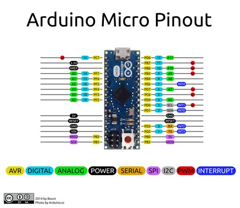
Arduino Leonardo Pinout Diagram
To better understand the layout and connections of the Arduino Leonardo, let’s take a look at its pinout diagram:
[Insert a clear and labeled pinout diagram of the Arduino Leonardo]

Digital Pins
The Arduino Leonardo features 20 digital input/output pins, labeled 0 to 13 and A0 to A5. These pins can be used for various purposes, such as reading digital inputs, controlling digital outputs, and utilizing PWM functionality.
Digital Pins 0 and 1 (RX and TX)
Pins 0 (RX) and 1 (TX) are used for serial communication. They are connected to the ATmega32u4’s hardware UART (Universal Asynchronous Receiver/Transmitter), allowing the board to communicate with other devices via a serial protocol.
Digital Pins 2 to 12
Pins 2 to 12 are general-purpose digital input/output pins. They can be configured as either inputs or outputs using the pinMode() function in Arduino sketches. These pins can be used for tasks such as reading switches, controlling LEDs, and interfacing with various Digital Sensors and actuators.
Digital Pin 13 (Built-in LED)
Pin 13 is connected to the built-in LED on the Arduino Leonardo board. This LED is useful for debugging and indicating the status of your sketch. You can control the LED using the digitalWrite() function.

Analog Pins
The Arduino Leonardo has 12 analog input pins, labeled A0 to A11. These pins can read analog voltages between 0V and 5V and convert them into digital values ranging from 0 to 1023.
Analog Pins A0 to A5
Pins A0 to A5 are dedicated analog input pins. They can be used to read analog sensors, such as potentiometers, light sensors, and temperature sensors. These pins have a resolution of 10 bits, meaning they can detect 1,024 different voltage levels.
Analog Pins A6 to A11
Pins A6 to A11 are additional analog input pins that are multiplexed with digital pins 4, 6, 8, 9, 10, and 12, respectively. These pins can be used as either analog inputs or digital input/output pins, depending on your project requirements.

PWM Pins
The Arduino Leonardo has 7 pins that support Pulse Width Modulation (PWM) functionality. PWM allows you to generate analog-like signals using digital pins, which is useful for controlling the brightness of LEDs, the speed of motors, and creating audio tones.
PWM Pins 3, 5, 6, 9, 10, 11, and 13
Pins 3, 5, 6, 9, 10, 11, and 13 support PWM output. These pins can be used to generate PWM signals with a resolution of 8 bits, providing 256 different duty cycle levels. To use PWM on these pins, you can utilize the analogWrite() function in your Arduino sketches.
Special Function Pins
The Arduino Leonardo has several pins with special functions that are worth noting:
I2C Pins (SDA and SCL)
Pins 2 (SDA) and 3 (SCL) are used for I2C (Inter-Integrated Circuit) communication. I2C is a synchronous serial communication protocol that allows multiple devices to communicate with each other using just two wires. These pins are commonly used to connect I2C-compatible sensors, displays, and other peripherals to the Arduino Leonardo.
SPI Pins (MISO, MOSI, SCK, SS)
The Arduino Leonardo supports SPI (Serial Peripheral Interface) communication through the following pins:
– MISO (Master In Slave Out): Pin 12
– MOSI (Master Out Slave In): Pin 11
– SCK (Serial Clock): Pin 13
– SS (Slave Select): Pin 10
SPI is a synchronous serial communication protocol that enables high-speed data transfer between the microcontroller and peripheral devices. It is commonly used for interfacing with sensors, memory devices, and displays.
External Interrupts (INT0 and INT1)
The Arduino Leonardo has two external interrupt pins:
– INT0: Pin 3
– INT1: Pin 2
These pins can be used to trigger interrupts based on external events, such as a change in the state of a pin or a specific voltage level. Interrupts allow the microcontroller to respond quickly to external events without the need for constant polling.
Power Pins
The Arduino Leonardo has several pins dedicated to power supply and ground connections:
VIN Pin
The VIN pin is used to supply external power to the Arduino Leonardo when it is not powered via USB. The acceptable voltage range for the VIN pin is 6V to 12V. When power is supplied through the VIN pin, the on-board voltage regulator steps it down to 5V for the microcontroller and other components.
5V Pin
The 5V pin provides a regulated 5V power supply to the Arduino Leonardo and connected peripherals. This pin can be used to power external components that require a stable 5V supply. It is important to note that the maximum current draw from the 5V pin should be limited to avoid damaging the voltage regulator.
3.3V Pin
The 3.3V pin provides a regulated 3.3V power supply, which can be used to power external components that require a lower voltage. This pin is useful when interfacing with sensors or modules that operate at 3.3V logic levels.
GND Pins
The GND pins are the ground connections for the Arduino Leonardo. They provide a common reference point for all the voltages in the circuit. It is essential to connect the GND pins of the Arduino Leonardo to the ground of any external components or power supplies to ensure proper operation and avoid potential damage.
Reset Button and ICSP Header
The Arduino Leonardo features a reset button and an ICSP (In-Circuit Serial Programming) header:
Reset Button
The reset button allows you to manually reset the Arduino Leonardo, restarting the execution of the currently loaded sketch. Pressing the reset button is equivalent to power cycling the board.
ICSP Header
The ICSP header is a 6-pin connector that allows for direct programming of the ATmega32u4 microcontroller using an external programmer. This header is useful for advanced users who want to upload bootloaders or perform low-level programming tasks.
Example Projects and Connections
Now that we have explored the Arduino Leonardo pinout, let’s look at a few example projects and how to make the necessary connections:
Controlling an LED
To control an LED using the Arduino Leonardo, you can follow these steps:
- Connect the anode (positive leg) of the LED to a digital pin, such as pin 13, through a current-limiting resistor (usually 220Ω to 1kΩ).
- Connect the cathode (negative leg) of the LED to the GND pin.
- In your Arduino sketch, use the
pinMode()function to set the digital pin as an output. - Use the
digitalWrite()function to turn the LED on or off by setting the pin to HIGH or LOW, respectively.
Reading an Analog Sensor
To read an analog sensor, such as a potentiometer, using the Arduino Leonardo, follow these steps:
- Connect the potentiometer’s middle pin (wiper) to an analog input pin, such as A0.
- Connect one of the outer pins to the 5V pin and the other outer pin to the GND pin.
- In your Arduino sketch, use the
analogRead()function to read the voltage value from the analog pin. - The
analogRead()function will return a value between 0 and 1023, representing the voltage level on the pin.
Using I2C Communication
To communicate with an I2C device, such as an OLED display, using the Arduino Leonardo, follow these steps:
- Connect the SDA pin of the I2C device to the SDA pin (pin 2) of the Arduino Leonardo.
- Connect the SCL pin of the I2C device to the SCL pin (pin 3) of the Arduino Leonardo.
- Connect the VCC and GND pins of the I2C device to the appropriate power and ground pins on the Arduino Leonardo.
- In your Arduino sketch, include the necessary libraries for the I2C device (e.g., Wire.h for general I2C communication, Adafruit_SSD1306.h for OLED displays).
- Use the library functions to initialize the I2C communication and interact with the device.
Troubleshooting Common Issues
When working with the Arduino Leonardo, you may encounter some common issues. Here are a few troubleshooting tips:
USB Port Not Recognized
If your computer does not recognize the Arduino Leonardo when you connect it via USB, try the following:
- Make sure you have selected the correct board type (Arduino Leonardo) in the Arduino IDE.
- Check if the drivers for the Arduino Leonardo are properly installed on your system.
- Try using a different USB cable or a different USB port on your computer.
Sketch Upload Fails
If you encounter errors while uploading a sketch to the Arduino Leonardo, consider these solutions:
- Verify that you have selected the correct board type and serial port in the Arduino IDE.
- Press and hold the reset button on the Arduino Leonardo while clicking the upload button in the Arduino IDE. Release the reset button when the upload starts.
- Make sure there are no syntax errors in your sketch and that all the required libraries are properly installed.
Unexpected Behavior
If your Arduino Leonardo is behaving unexpectedly or not responding as intended, try these troubleshooting steps:
- Double-check your wiring connections to ensure everything is properly connected.
- Verify that you are using the correct pins in your sketch and that they match the physical connections.
- Check for any short circuits or loose connections that may be causing issues.
- Use serial communication and print statements to debug your sketch and identify the source of the problem.
Frequently Asked Questions (FAQ)
-
What is the difference between the Arduino Leonardo and the Arduino Uno?
The main difference between the Arduino Leonardo and the Arduino Uno is the microcontroller they use. The Leonardo uses the ATmega32u4, while the Uno uses the ATmega328P. The Leonardo has built-in USB communication, allowing it to emulate a keyboard and mouse, whereas the Uno requires a separate serial-to-USB chip. Additionally, the Leonardo has a smaller form factor and a different pinout compared to the Uno. -
Can I use Arduino Uno shields with the Arduino Leonardo?
Most Arduino Uno shields are compatible with the Arduino Leonardo, as they share a similar form factor and pin layout. However, there may be some differences in pin assignments, particularly for the SDA and SCL pins used for I2C communication. It’s always a good idea to check the shield’s documentation and compare it with the Leonardo’s pinout to ensure compatibility. -
How do I update the firmware on the Arduino Leonardo?
To update the firmware on the Arduino Leonardo, you can use the Arduino IDE. Make sure you have the latest version of the IDE installed. Connect your Leonardo to your computer via USB, select the appropriate board type and serial port in the IDE, and then click on “Burn Bootloader” under the “Tools” menu. This will update the firmware on your Leonardo to the latest version. -
Can I use the Arduino Leonardo for real-time applications?
The Arduino Leonardo, like most Arduino boards, is not designed for hard real-time applications that require precise timing and deterministic behavior. The Leonardo’s microcontroller runs at 16 MHz and uses a non-real-time operating system, which means there can be slight variations in execution timing. For applications with strict real-time requirements, it’s recommended to use dedicated real-time systems or microcontrollers specifically designed for such purposes. -
What is the maximum current that the Arduino Leonardo can provide on its pins?
The maximum current that each pin on the Arduino Leonardo can provide is 40 mA. However, it is recommended to keep the current draw below 20 mA per pin to avoid potential damage to the microcontroller. If you need to control devices that require higher currents, it’s advisable to use external drivers or transistors to handle the higher current loads.
Conclusion
The Arduino Leonardo is a versatile and powerful microcontroller board that offers a wide range of features and connectivity options. By understanding its pinout and the functions of each pin, you can effectively utilize the board’s capabilities in your projects.
Whether you are a beginner or an experienced developer, the Arduino Leonardo provides a user-friendly platform for prototyping and building interactive electronic projects. With its extensive library support and active community, you can find ample resources and inspiration to bring your ideas to life.
Remember to refer to the Arduino Leonardo pinout diagram and the information provided in this article when planning your projects and making connections. By following best practices and troubleshooting common issues, you can ensure a smooth and successful development experience with the Arduino Leonardo.
Happy tinkering and creating with the Arduino Leonardo!
[Insert a relevant and visually appealing image related to the Arduino Leonardo or its applications]
No responses yet