Introduction to Antenna Design and RF Layout
Antenna design and RF layout are critical aspects of wireless communication systems. The antenna is responsible for transmitting and receiving electromagnetic waves, while the RF layout ensures that the signals are properly routed and conditioned. Proper antenna design and RF layout are essential for achieving optimal system performance, including high efficiency, wide bandwidth, and low noise.
In this article, we will provide comprehensive guidelines for antenna design and RF layout. We will cover the fundamental principles of antenna theory, including antenna types, radiation patterns, and impedance matching. We will also discuss the key considerations for RF layout, such as grounding, shielding, and signal integrity.
Antenna Theory Basics
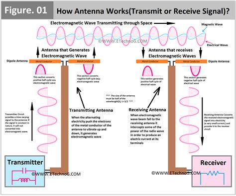
Antennas are devices that convert electrical signals into electromagnetic waves and vice versa. The basic principles of antenna theory involve understanding the properties of electromagnetic waves and how they interact with antennas.
Electromagnetic Waves
Electromagnetic waves are created by the oscillation of electric and magnetic fields. They propagate through space at the speed of light and can be characterized by their frequency, wavelength, and amplitude. The frequency of an electromagnetic wave determines its position in the electromagnetic spectrum, which includes radio waves, microwaves, infrared, visible light, ultraviolet, X-rays, and gamma rays.
Antenna Types
There are many different types of antennas, each with its own unique properties and applications. Some common types of antennas include:
-
Dipole Antennas: Dipole antennas consist of two conductors that are fed with a signal. They are simple and effective for many applications, but have limited bandwidth and directivity.
-
Monopole Antennas: Monopole antennas are similar to dipole antennas, but use a ground plane instead of a second conductor. They are commonly used in mobile devices and other portable applications.
-
Patch Antennas: Patch antennas are flat, rectangular antennas that are commonly used in microwave and millimeter-wave applications. They have a low profile and can be easily integrated into printed circuit boards.
-
Horn Antennas: Horn antennas are widely used in satellite communications and radar systems. They have high gain and directivity, but are relatively large and bulky.
-
Yagi-Uda Antennas: Yagi-Uda antennas consist of an array of dipole elements that are designed to enhance directivity and gain. They are commonly used in television reception and point-to-point communications.
Radiation Patterns
The radiation pattern of an antenna describes the spatial distribution of the electromagnetic energy it radiates. The radiation pattern is typically represented by a three-dimensional plot that shows the relative strength of the radiated signal in different directions.
The radiation pattern of an antenna is determined by its geometry and the frequency of the signal it is transmitting or receiving. Some common types of radiation patterns include:
-
Omnidirectional: Omnidirectional antennas radiate equally in all directions in a single plane. They are commonly used in applications where coverage is needed in all directions, such as in wireless access points.
-
Directional: Directional antennas concentrate their radiation in a specific direction. They are used in applications where high gain and long-range communication are required, such as in point-to-point links.
-
Isotropic: An isotropic antenna is a theoretical antenna that radiates equally in all directions. It is used as a reference for measuring the gain and directivity of real antennas.
Impedance Matching
Impedance matching is the process of matching the impedance of an antenna to the impedance of the transmission line or device it is connected to. Proper impedance matching is essential for maximizing power transfer and minimizing signal reflections.
The impedance of an antenna is determined by its geometry and the frequency of the signal it is transmitting or receiving. The impedance of a transmission line is determined by its characteristic impedance, which is typically 50 ohms for most RF applications.
To achieve impedance matching, a matching network can be used to transform the impedance of the antenna to match the impedance of the transmission line. Common matching networks include:
-
L-Networks: L-networks consist of a single inductor and capacitor and can be used to match a wide range of impedances.
-
Pi-Networks: Pi-networks consist of two capacitors and an inductor and provide a wider matching range than L-networks.
-
Stub Matching: Stub matching uses a short or open-circuited transmission line stub to cancel out the reactive component of the antenna impedance.
RF Layout Considerations
RF layout is the process of designing and implementing the physical layout of an RF circuit. Proper RF layout is essential for minimizing signal loss, reducing interference, and ensuring reliable operation.
Grounding
Grounding is the process of providing a low-impedance path for current to flow between different parts of a circuit. In RF circuits, proper grounding is essential for minimizing ground loops, reducing electromagnetic interference (EMI), and ensuring stable operation.
There are several key considerations for grounding in RF layouts:
-
Ground Planes: A solid ground plane should be used to provide a low-impedance path for return currents. The ground plane should be as large as possible and should be connected to the circuit ground at multiple points.
-
Via Stitching: Via stitching is the process of placing multiple vias between the ground plane and the component ground pads. This helps to minimize ground inductance and ensure a low-impedance path for return currents.
-
Grounding of Sensitive Components: Sensitive components, such as amplifiers and oscillators, should be grounded directly to the ground plane using short, low-inductance connections.
Shielding
Shielding is the process of enclosing a circuit or component in a conductive material to reduce electromagnetic interference (EMI) and radio frequency interference (RFI). Shielding is essential for preventing interference between different parts of a circuit and ensuring reliable operation.
There are several key considerations for shielding in RF layouts:
-
Shielding Materials: Shielding materials should be selected based on the frequency range of the circuit and the level of shielding required. Common shielding materials include copper, aluminum, and conductive plastics.
-
Shielding Enclosures: Shielding enclosures should be designed to provide a continuous conductive barrier around the circuit. The enclosure should be grounded to the circuit ground and should have no gaps or openings that could allow EMI to escape.
-
Gaskets and Seals: Gaskets and seals should be used to ensure a tight fit between the shielding enclosure and the circuit board. Conductive gaskets, such as those made from conductive foam or fabric, can be used to provide a low-impedance path for return currents.
Signal Integrity
Signal integrity is the process of ensuring that signals are transmitted and received without distortion or loss. In RF circuits, signal integrity is essential for maintaining the quality and reliability of the transmitted signal.
There are several key considerations for signal integrity in RF layouts:
-
Transmission Lines: Transmission lines should be designed to have a characteristic impedance that matches the impedance of the source and load. The length of the transmission line should be kept as short as possible to minimize signal loss.
-
Impedance Matching: Impedance matching should be used to ensure maximum power transfer and minimum signal reflections. Matching networks can be used to transform the impedance of the source and load to match the characteristic impedance of the transmission line.
-
Crosstalk: Crosstalk is the unwanted coupling of signals between adjacent traces or components. Crosstalk can be minimized by using proper spacing between traces, avoiding parallel runs of traces, and using guard traces or ground planes to provide shielding.
Antenna Design Guidelines
Antenna design is a complex process that requires careful consideration of many different factors. Here are some general guidelines for designing antennas:
Choose the Right Antenna Type
The first step in antenna design is to choose the right type of antenna for the application. The choice of antenna type will depend on factors such as the frequency range, bandwidth, gain, and directivity required.
Some common types of antennas and their typical applications are:
| Antenna Type | Typical Applications |
|---|---|
| Dipole | FM radio, television, Wi-Fi |
| Monopole | Mobile devices, wireless access points |
| Patch | Microwave and millimeter-wave applications |
| Horn | Satellite communications, radar |
| Yagi-Uda | Television reception, point-to-point links |
Consider the Radiation Pattern
The radiation pattern of an antenna determines the spatial distribution of the radiated energy. The radiation pattern should be chosen based on the coverage and directivity requirements of the application.
For example, an omnidirectional antenna may be preferred for applications where coverage is needed in all directions, while a directional antenna may be preferred for applications where high gain and long-range communication are required.
Optimize the Antenna Geometry
The geometry of an antenna plays a critical role in determining its performance. The size, shape, and material of the antenna should be optimized to achieve the desired frequency response, bandwidth, and efficiency.
Some common techniques for optimizing antenna geometry include:
- Adjusting the length and width of the antenna elements
- Using tapered or stepped structures to improve bandwidth
- Adding parasitic elements to enhance directivity and gain
- Using dielectric loading to reduce the size of the antenna
Ensure Proper Impedance Matching
Proper impedance matching is essential for maximizing power transfer and minimizing signal reflections. The impedance of the antenna should be matched to the impedance of the transmission line or device it is connected to.
Impedance matching can be achieved using a variety of techniques, such as:
- Using a matching network to transform the antenna impedance to match the transmission line impedance
- Adjusting the geometry of the antenna to achieve the desired impedance
- Using a balun to convert between balanced and unbalanced impedances
Minimize Losses and Interference
Losses and interference can significantly degrade the performance of an antenna. Some common sources of losses and interference include:
- Ohmic losses in the antenna material and conductors
- Dielectric losses in the substrate and insulation materials
- Reflection losses due to impedance mismatches
- Coupling and crosstalk between adjacent antennas or circuits
To minimize losses and interference, the following techniques can be used:
- Use low-loss materials for the antenna and substrate
- Minimize the length of the feed line and use a high-quality connector
- Use shielding and grounding techniques to reduce coupling and crosstalk
- Use filtering and impedance matching to reduce reflections and interference
RF Layout Guidelines
RF layout is the process of designing and implementing the physical layout of an RF circuit. Here are some general guidelines for RF layout:
Use a Solid Ground Plane
A solid ground plane is essential for providing a low-impedance return path for currents and minimizing ground loops and EMI. The ground plane should be as large as possible and should be connected to the circuit ground at multiple points using via stitching.
Minimize the Length of Signal Paths
The length of signal paths should be minimized to reduce losses and signal distortion. This can be achieved by placing components as close together as possible and using direct connections instead of long traces.
Use Proper Transmission Line Routing
Transmission lines should be routed carefully to maintain a constant characteristic impedance and minimize reflections and crosstalk. Some common techniques for routing transmission lines include:
- Using a coplanar waveguide or stripline structure to provide shielding and constant impedance
- Avoiding sharp bends or discontinuities in the transmission line
- Using via fences or guard traces to provide isolation between adjacent signals
Use Proper Shielding and Grounding
Shielding and grounding are essential for reducing EMI and ensuring stable operation. Some common techniques for shielding and grounding include:
- Using shielding enclosures and gaskets to provide a continuous conductive barrier around the circuit
- Grounding sensitive components directly to the ground plane using short, low-inductance connections
- Using via stitching to provide a low-impedance path for return currents
Consider Signal Integrity
Signal integrity is essential for maintaining the quality and reliability of the transmitted signal. Some common techniques for ensuring signal integrity include:
- Using impedance matching to ensure maximum power transfer and minimum reflections
- Minimizing crosstalk by using proper spacing and isolation techniques
- Using filtering and equalization to compensate for losses and distortion in the signal path
Conclusion
Antenna design and RF layout are critical aspects of wireless communication systems. Proper antenna design and RF layout are essential for achieving optimal system performance, including high efficiency, wide bandwidth, and low noise.
When designing antennas, it is important to choose the right antenna type, consider the radiation pattern, optimize the antenna geometry, ensure proper impedance matching, and minimize losses and interference.
When designing RF layouts, it is important to use a solid ground plane, minimize the length of signal paths, use proper transmission line routing, use proper shielding and grounding, and consider signal integrity.
By following these guidelines and techniques, designers can create high-performance wireless communication systems that meet the needs of a wide range of applications.
Frequently Asked Questions
Q: What is the difference between a dipole and a monopole antenna?
A: A dipole antenna consists of two conductors that are fed with a signal, while a monopole antenna uses a single conductor and a ground plane. Monopole antennas are commonly used in mobile devices and other portable applications, while dipole antennas are used in a wide range of applications, including FM radio and television.
Q: What is the purpose of impedance matching in antenna design?
A: Impedance matching is used to ensure maximum power transfer and minimum signal reflections between the antenna and the transmission line or device it is connected to. Proper impedance matching is essential for achieving high efficiency and minimizing losses in the system.
Q: What is the difference between EMI and RFI?
A: EMI (electromagnetic interference) and RFI (radio frequency interference) are both types of interference that can degrade the performance of electronic systems. EMI refers to interference caused by electromagnetic fields, while RFI refers specifically to interference caused by radio frequency signals.
Q: What is the purpose of via stitching in RF layout?
A: Via stitching is the process of placing multiple vias between the ground plane and the component ground pads. This helps to minimize ground inductance and ensure a low-impedance path for return currents, which is essential for minimizing EMI and ensuring stable operation.
Q: What is the difference between a coplanar waveguide and a stripline?
A: A coplanar waveguide is a type of transmission line that consists of a single conductor with two ground planes on either side, while a stripline is a type of transmission line that consists of a single conductor sandwiched between two ground planes. Both structures provide shielding and constant impedance, but striplines offer better isolation and less radiation than coplanar waveguides.
No responses yet