Introduction to AM Radio Schematics
An AM radio schematic is a diagram that represents the electrical components and connections of an amplitude modulation (AM) radio circuit. These schematics serve as a visual guide for understanding, building, and troubleshooting AM radio circuits. In this article, we will explore the basics of AM radio schematics, their components, and how to create simple circuit diagrams.
What is an AM Radio?
An AM radio is a type of radio that receives amplitude modulation signals. These signals are transmitted by radio stations and contain audio information that is decoded by the radio’s circuitry. AM radio operates in the frequency range of 535 kHz to 1605 kHz, also known as the medium wave (MW) band.
The Importance of Schematics in AM Radio Design
Schematics play a crucial role in the design and construction of AM radio circuits. They provide a clear and concise representation of the circuit’s components and their interconnections. By following a well-designed schematic, engineers and hobbyists can build functional AM radios and troubleshoot any issues that may arise.
Components of an AM Radio Schematic
An AM radio schematic typically includes several key components that work together to receive and process AM signals. Let’s take a closer look at each of these components:
1. Antenna
The antenna is responsible for receiving the AM radio signals from the environment. It is usually a long wire or a ferrite rod antenna that is tuned to the desired frequency range.
2. Tuning Capacitor
The tuning capacitor is a variable capacitor that allows the user to select the desired AM station. It works in conjunction with the antenna to form a resonant circuit that is sensitive to the desired frequency.
3. RF Amplifier
The radio frequency (RF) amplifier is responsible for amplifying the weak AM signal received by the antenna. It helps to improve the signal-to-noise ratio and provides a stronger signal for further processing.
4. Mixer
The mixer is a circuit that combines the amplified RF signal with a local oscillator signal to produce an intermediate frequency (IF) signal. This process is known as heterodyning and is essential for AM demodulation.
5. Local Oscillator
The local oscillator is a circuit that generates a stable, high-frequency signal that is mixed with the RF signal in the mixer stage. The frequency of the local oscillator is typically 455 kHz above or below the desired AM station frequency.
6. IF Amplifier
The intermediate frequency (IF) amplifier is responsible for amplifying the IF signal generated by the mixer. It provides additional gain and selectivity to the AM signal before it is demodulated.
7. Detector
The detector, also known as the demodulator, is a circuit that extracts the audio information from the amplified IF signal. It typically uses a diode to rectify the signal and a low-pass filter to remove any high-frequency components.
8. Audio Amplifier
The audio amplifier is the final stage in the AM radio schematic. It amplifies the demodulated audio signal to a level suitable for driving a speaker or headphones.

Creating Simple AM Radio Schematics
Now that we have a basic understanding of the components found in an AM radio schematic, let’s explore how to create simple circuit diagrams.
Step 1: Identify the Components
The first step in creating an AM radio schematic is to identify the necessary components. These typically include:
- Antenna
- Tuning capacitor
- RF amplifier
- Mixer
- Local oscillator
- IF amplifier
- Detector
- Audio amplifier
Step 2: Determine the Component Values
Once you have identified the components, you need to determine their values. This includes the capacitance of the tuning capacitor, the inductance of the antenna, the gain of the amplifiers, and the frequency of the local oscillator. These values can be obtained from datasheets, reference designs, or through calculations based on the desired performance characteristics.
Step 3: Draw the Schematic
With the components and their values determined, you can now start drawing the schematic. Begin by placing the components on the diagram and connecting them according to their electrical relationships. Use standard schematic symbols to represent each component, such as:
- Resistors: Zigzag lines
- Capacitors: Two parallel lines
- Inductors: Coiled lines
- Diodes: Triangle with a line
- Transistors: Circle with three leads
Be sure to label each component with its value and any other relevant information.
Step 4: Add Power Supply and Ground Connections
An AM radio circuit requires a power supply to function. Add the necessary power supply connections to the schematic, typically labeling them as VCC or VDD for positive supply and GND for ground. Make sure to connect the appropriate components to the power supply and ground.
Step 5: Review and Refine
Once you have completed the initial schematic, review it carefully for any errors or omissions. Verify that all connections are correct and that the component values are appropriate. If necessary, refine the schematic by making any needed adjustments or additions.

Example AM Radio Schematic
To better understand the process of creating an AM radio schematic, let’s look at a simple example. The following table represents the components and their values for a basic AM radio circuit:
| Component | Value |
|---|---|
| Antenna | Ferrite rod |
| Tuning capacitor | 10-365 pF |
| RF amplifier | 2N3904 |
| Mixer | 2N3904 |
| Local oscillator | 455 kHz |
| IF amplifier | 2N3904 |
| Detector | 1N60 diode |
| Audio amplifier | LM386 |
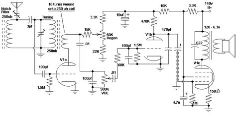
Using these components and values, we can create a simple AM radio schematic as shown below:
[Simplified AM Radio Schematic Diagram]
In this schematic, the antenna and tuning capacitor form a resonant circuit that is tuned to the desired AM station. The RF amplifier, mixer, and local oscillator work together to convert the AM signal to an IF signal. The IF amplifier provides additional gain, and the detector demodulates the audio signal. Finally, the audio amplifier drives a speaker or headphones.

Tips for Designing AM Radio Schematics
When designing AM radio schematics, keep the following tips in mind:
-
Use a clear and consistent layout: Arrange the components in a logical flow, with signal paths running from left to right or top to bottom. Use consistent spacing and alignment to improve readability.
-
Provide adequate power supply decoupling: Include Bypass Capacitors near the power supply pins of active components to reduce noise and ensure stable operation.
-
Pay attention to component selection: Choose components that are appropriate for the desired frequency range, gain, and power requirements. Consider factors such as tolerance, stability, and cost.
-
Test and verify the circuit: Once you have built the circuit based on the schematic, test it thoroughly to ensure that it functions as expected. Use an oscilloscope or signal generator to verify the signal levels and frequencies at various points in the circuit.
-
Document and annotate the schematic: Include relevant information such as component values, pin numbers, and voltage levels. Add notes or comments to clarify the purpose of each section of the circuit.
Frequently Asked Questions (FAQ)
- What is the purpose of the tuning capacitor in an AM radio schematic?
-
The tuning capacitor, in combination with the antenna, forms a resonant circuit that is tuned to the desired AM station frequency. By adjusting the capacitance, the user can select different stations within the AM band.
-
What is the role of the mixer in an AM radio circuit?
-
The mixer combines the amplified RF signal from the antenna with a local oscillator signal to produce an intermediate frequency (IF) signal. This process, known as heterodyning, is essential for AM demodulation and allows the radio to effectively process the received signal.
-
Why is the IF amplifier important in an AM radio schematic?
-
The IF amplifier provides additional gain and selectivity to the AM signal after it has been converted to the intermediate frequency by the mixer. It helps to improve the signal-to-noise ratio and ensures that the demodulator receives a strong and clear signal.
-
What is the purpose of the detector in an AM radio circuit?
-
The detector, also known as the demodulator, extracts the audio information from the amplified IF signal. It typically uses a diode to rectify the signal and a low-pass filter to remove any high-frequency components, leaving only the original audio signal.
-
Can I use different component values than those shown in the example schematic?
- Yes, the component values in the example schematic are just one possible configuration. You can modify the values based on your specific requirements, such as the desired frequency range, gain, or power consumption. However, be sure to select components that are appropriate for the intended application and verify the circuit’s performance through testing.
Conclusion
AM radio schematics provide a essential foundation for understanding and designing amplitude modulation radio circuits. By familiarizing yourself with the key components and their functions, you can create simple and effective AM radio designs. Remember to follow best practices for schematic layout, component selection, and testing to ensure optimal performance. With practice and experimentation, you can develop more advanced AM radio circuits and explore the fascinating world of radio electronics.
No responses yet