Introduction to Ethernet PHY Design
Ethernet is the most widely used wired networking technology for local area networks (LANs). At the heart of every Ethernet connection is the physical layer transceiver, or PHY. The PHY is responsible for transmitting and receiving data over the physical medium, such as twisted pair copper cabling.
One popular Ethernet PHY is the DP83848C from Texas Instruments. This article will provide a comprehensive guide on how to design with the DP83848C to create robust, high-performance Ethernet networks.
Key Features of the DP83848C Ethernet PHY
The DP83848C is a single-port 10/100 Mbps Ethernet physical layer transceiver that supports both half-duplex and full-duplex operation. Some of its key features include:
- IEEE 802.3 compliant
- Supports 10BASE-T and 100BASE-TX standards
- Integrated line-side termination resistors
- Low power consumption
- Robust cable diagnostics and power saving modes
- RMII, MII and SNI serial interfaces
- Industrial temperature range from -40°C to 85°C
These features make the DP83848C well-suited for a wide range of Ethernet applications, from consumer devices to industrial equipment.
DP83848C Block Diagram and Pin Description
To understand how to design with the DP83848C, it’s helpful to first examine its internal architecture and pin configuration.
Block Diagram
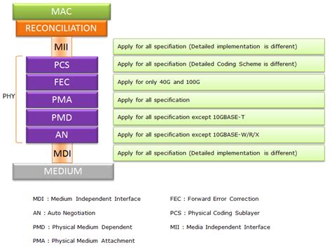
The following block diagram shows the major functional units inside the DP83848C:
The key blocks include:
- 10/100 Mbps Ethernet Media Access Controller (MAC) interface
- 10BASE-T/100BASE-TX transmit and receive function
- Physical Media Attachment (PMA) sublayer
- Physical Medium Dependent (PMD) sublayer
- Management Data Input/Output (MDIO) interface
- Configuration registers
Pin Description
The DP83848C comes in a 48-pin TQFP package. Here is a brief description of the main pins:
| Pin Name | Type | Description |
|---|---|---|
| TX_CLK | I | Transmit clock (2.5/25 MHz) |
| TXD[3:0] | I | Transmit data |
| TX_EN | I | Transmit enable |
| TX_ER | I | Transmit error |
| RX_CLK | O | Receive clock (2.5/25 MHz) |
| RXD[3:0] | O | Receive data |
| RX_DV | O | Receive data valid |
| RX_ER | O | Receive error |
| CRS | O | Carrier sense |
| COL | O | Collision detect |
| MDC | I | Management data clock |
| MDIO | I/O | Management data input/output |
| RESET_N | I | Hardware reset |
| LED_SPEED | O | 100 Mb/s speed indicator |
| LED_LINK | O | Valid link established |
| X1 | I | 25 MHz crystal input 1 |
| X2 | I | 25 MHz crystal input 2 |
For the full pin descriptions, refer to the DP83848C datasheet.

Interfacing the DP83848C with an Ethernet MAC
The DP83848C supports three standard Media Independent Interfaces (MII) to connect to an Ethernet MAC:
- Media Independent Interface (MII)
- Reduced Media Independent Interface (RMII)
- Serial-MII (SMII)
The MII uses 4-bit wide transmit and receive data buses, while RMII and SMII use 2-bit and 1-bit buses respectively to reduce pin count. The interface selection is done via the MODESEL strapping option pins.
Here is an example connection diagram for the MII interface:
        MAC                   PHY
        ---                   ---
TXD[3:0]  -->        TXD[3:0]
TX_EN     -->           TX_EN
TX_ER     -->           TX_ER
TX_CLK   <---          TX_CLK
RXD[3:0] <---        RXD[3:0]
RX_DV    <---           RX_DV
RX_ER    <---           RX_ER
RX_CLK   <---          RX_CLK
  CRS    <---             CRS
  COL    <---             COL
  MDC     -->             MDC
 MDIO    <-->            MDIO
The DP83848C samples the transmit data (TXD) on the rising edge of TX_CLK when TX_EN is asserted. The receive data (RXD) is driven on the rising edge of RX_CLK along with RX_DV.
To access the DP83848C’s configuration registers, the MAC uses the MDIO serial management interface. The MDC clock is typically 2.5 MHz. The ST (start of frame), OP (opcode), PHYAD (PHY address), REGAD (register address), and TA (turnaround) bits control the MDIO read/write operations.
Configuring the DP83848C
The DP83848C has several internal registers that control its operation and status reporting. These registers conform to the IEEE 802.3 standard and are summarized below:
| Address | Name | Description |
|---|---|---|
| 0 | Basic Control | Mode/reset control |
| 1 | Basic Status | Link/error status |
| 2 | PHY Identifier 1 | OUI bits 3:18 |
| 3 | PHY Identifier 2 | OUI bits 19:24 |
| 4 | Auto-Negotiation Advertisement | Link capabilities |
| 5 | Auto-Negotiation Link Partner | Link partner ability |
| 6 | Auto-Negotiation Expansion | Extended status info |
| 16 | Extended Control | Enhanced features |
| 17 | Extended Status | Cable diagnostics |
| 18 | PHY Interrupt Control/Status | Interrupt event ctrl |
| … |
Some of the key configuration steps are:
-
Reset the PHY by setting bit 15 of the Basic Control register. This puts the PHY in a known state.
-
Set up the desired line speed and duplex mode through auto-negotiation or forced settings via the Basic Control register.
-
Check the Basic Status register to verify link establishment and auto-negotiation results.
-
Enable enhanced features like cable diagnostics, power saving modes, and interrupt events using the extended registers.
-
Monitor the receive error count and link status to detect cable or connectivity issues.
Refer to the DP83848C datasheet and register descriptions for the full configuration details.
PCB Layout Considerations
Careful PCB layout is critical for Ethernet PHY designs to ensure signal integrity, minimize emissions, and pass compliance testing. Here are some guidelines:
-
Keep the DP83848C as close as possible to the Ethernet connector. The total trace length from PHY to connector should be less than 4 inches.
-
Use controlled impedance traces (100 ohm differential) for the MDI signals. Length match the pairs to within 50 mils.
-
Maintain a continuous ground plane underneath the PHY and MDI traces. Avoid splitting the ground as this can cause common-mode noise.
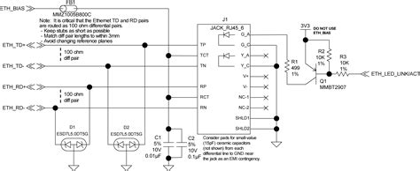
-
Place the transformer and termination close to the PHY pins. Use a Bob Smith termination for baseline wander correction.
-
Keep the 25 MHz crystal traces short and away from potential aggressors. Provide a local ground plane.
-
Use a 4-layer PCB with solid power and ground planes for best performance. Decouple the PHY power pins with a mix of bulk and ceramic capacitors.
-
Route the MDIO/MDC signals away from the MDI lines to prevent crosstalk. Use series resistors if long traces are unavoidable.
-
Include pads for the media converter center-taps (if applicable) and the cable shield connection.
Following these guidelines will help ensure your Ethernet PHY design works reliably.
Magnetics Selection
The Ethernet magnetics, or transformer, provides isolation and common-mode rejection between the PHY and the cable. The DP83848C requires a 1:1 turns ratio transformer with 350 uH minimum inductance.
Key parameters to consider when selecting the magnetics include:
- Turns ratio (1:1 for 10/100 Mbps Ethernet)
- Inductance (350 uH min per IEEE 802.3)
- Current rating (IDC > 200 mA)
- Return loss (> 16 dB @ 100 MHz)
- Insertion loss (< 1 dB @ 100 MHz)
- Hi-pot rating (1500 Vrms for 60 sec)
- Operating temperature range
- Packaging (SMD or through-hole)
Popular magnetics vendors include Pulse Electronics, Wurth Electronics, and Halo Electronics. Many vendors offer Ethernet magnetics with built-in termination resistors and Bob Smith circuitry.
Ethernet Compliance Testing
To ensure interoperability and robustness, Ethernet designs must pass a series of compliance tests defined by the IEEE and other standards bodies. Some of the key tests include:
- TP-PMD transmit waveform test
- Jitter tolerance test
- Transmitter clock frequency test
- Return loss test
- Receiver BER test
- Cable stress test
- Emission and immunity tests (FCC, CISPR)
Specialized test equipment like the Teledyne LeCroy Frontline Ethernet testers are used to perform these compliance tests. It’s recommended to budget for compliance testing and allocate time in the project schedule to address any issues.
While the DP83848C is a robust and compliant PHY, careful system design and PCB layout are still required to pass all tests. Pre-compliance testing during development can catch issues early and reduce the risk of failing formal compliance testing.
FAQ
Q: What is the difference between 10BASE-T and 100BASE-TX Ethernet?
A: 10BASE-T provides 10 Mbps data rate over Category 3 or better twisted pair cable, while 100BASE-TX provides 100 Mbps over Category 5 cable. 100BASE-TX uses a higher signaling frequency and more complex encoding schemes like 4B5B and MLT-3 to achieve faster speeds.
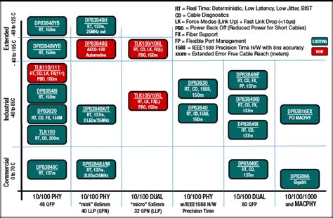
Q: Can the DP83848C support 1000BASE-T (Gigabit Ethernet)?
A: No, the DP83848C is a 10/100 Mbps Ethernet PHY. For Gigabit Ethernet, you would need a PHY like the DP83865 or DP83867 that supports the 1000BASE-T standard.
Q: What is auto-negotiation and how does it work?
A: Auto-negotiation is a protocol that allows two Ethernet devices to automatically exchange their capabilities and agree on the highest common denominator for speed and duplex mode. It is defined in Clause 28 of the IEEE 802.3 standard. The PHYs exchange 16-bit words called Link Code Words (LCW) that contain fields for selector, technology ability, and remote fault information.
Q: How do I access the DP83848C’s extended registers?
A: The extended registers are accessed using the same MDIO interface as the basic registers, but with a different opcode. Basic register accesses use an opcode of 00, while extended register accesses use an opcode of 11. Refer to the DP83848C datasheet for the full register map and access details.
Q: What is the purpose of the Bob Smith termination?
A: The Bob Smith termination is a resistor network that provides a DC bias current path between the transmit and receive signal pairs. This bias current is necessary to prevent baseline wander caused by the transformer high-pass response. Without the Bob Smith termination, long strings of 0s or 1s could cause the receiver to lose lock and corrupt the data. Most Ethernet magnetics include the Bob Smith termination built-in.
Conclusion
The DP83848C is a versatile and reliable Ethernet PHY that enables 10/100 Mbps networking in a wide range of applications. By following the guidelines in this article for interface selection, configuration, PCB layout, and magnetics selection, you can design a robust Ethernet solution that passes compliance testing and interoperates with other standard-compliant devices.
As Ethernet speeds continue to increase and new applications emerge, it’s important to stay up-to-date with the latest standards and best practices for PHY design. With the right tools and knowledge, you can create Ethernet networks that meet the demands of today and tomorrow.
No responses yet