What is Differential Line Impedance?
Differential line impedance, also known as characteristic impedance or surge impedance, is a crucial parameter in the design and analysis of transmission lines. It determines how signals propagate along the line and how reflections occur at discontinuities. In this article, we will delve into the concept of differential line impedance, its calculation, and its significance in various applications.
Understanding Transmission Lines
A transmission line is a structure that guides electromagnetic waves from one point to another. It consists of two or more parallel conductors separated by a dielectric medium. Common examples of transmission lines include coaxial cables, twisted pair cables, and microstrip lines.
The behavior of a transmission line is governed by its distributed parameters:
- Resistance (R) per unit length
- Inductance (L) per unit length
- Capacitance (C) per unit length
- Conductance (G) per unit length
These parameters determine the characteristic impedance and propagation constant of the line.
Characteristic Impedance
The characteristic impedance, denoted as Z0, is the ratio of the voltage to the current for a wave propagating along the transmission line. It is a complex quantity that depends on the frequency of the signal.
For a lossless transmission line (R = G = 0), the characteristic impedance is given by:
Z0 = sqrt(L/C)
where:
– L is the inductance per unit length
– C is the capacitance per unit length
For a lossy transmission line, the characteristic impedance is given by:
Z0 = sqrt((R + jωL) / (G + jωC))
where:
– R is the resistance per unit length
– L is the inductance per unit length
– G is the conductance per unit length
– C is the capacitance per unit length
– ω is the angular frequency (ω = 2πf)
The characteristic impedance determines the maximum power transfer and minimum reflections when the line is terminated with a load impedance equal to Z0.
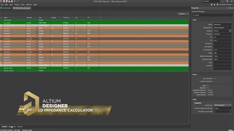
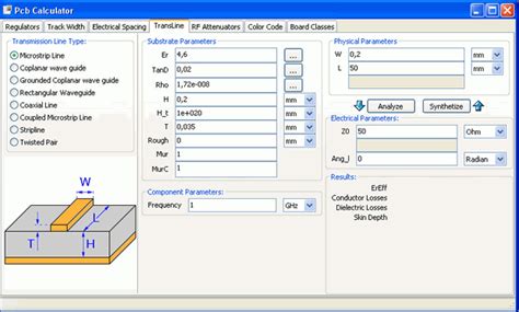
Impedance Calculator
To calculate the differential line impedance, you need to know the physical properties of the transmission line, such as the conductor dimensions, dielectric constant, and spacing between conductors. Here are the steps to calculate the impedance:
-
Determine the geometry of the transmission line (e.g., coaxial cable, microstrip line, etc.).
-
Identify the relevant dimensions and material properties:
- Conductor diameter (d)
- Dielectric constant (εr)
- Spacing between conductors (s)
-
Conductor thickness (t) for microstrip lines
-
Use the appropriate formula based on the transmission line geometry:
a. Coaxial Cable:
Z0 = (138 / sqrt(εr)) * log10(D/d)
where:
– D is the inner diameter of the outer conductor
– d is the outer diameter of the inner conductor
b. Microstrip Line:
Z0 = (87 / sqrt(εr + 1.41)) * ln(5.98h / (0.8w + t))
where:
– εr is the dielectric constant of the substrate
– h is the substrate thickness
– w is the width of the microstrip line
– t is the thickness of the microstrip line
- Substitute the values into the formula and calculate the characteristic impedance.
Here’s an example calculation for a coaxial cable:
Given:
- Inner conductor diameter (d) = 1 mm
- Outer conductor inner diameter (D) = 4 mm
- Dielectric constant (εr) = 2.3

Step 1: Identify the geometry
Coaxial cable

Step 2: Identify the dimensions and properties
d = 1 mm
D = 4 mm
εr = 2.3

Step 3: Use the coaxial cable formula
Z0 = (138 / sqrt(εr)) * log10(D/d)
   = (138 / sqrt(2.3)) * log10(4/1)
   = 90.7 Ω

Therefore, the characteristic impedance of the coaxial cable is approximately 90.7 Ω.
Applications of Differential Line Impedance
Understanding and calculating differential line impedance is essential in various fields, including:
- High-Speed Digital Design:
- Matching impedances between devices and transmission lines to minimize reflections and ensure signal integrity
-
Designing controlled impedance PCB traces for high-speed interfaces (e.g., USB, PCIe, HDMI)
-
RF and Microwave Engineering:
- Designing impedance-matched networks for maximum power transfer
- Minimizing reflections in antenna feedlines and microwave circuits
-
Optimizing the performance of filters, couplers, and power dividers
-
Telecommunications:
- Designing and deploying transmission lines for long-distance communication
-
Ensuring proper impedance matching in telephone networks and cable systems
-
Electromagnetics and Optics:
- Analyzing the propagation of electromagnetic waves in guided structures
- Designing impedance-matched optical waveguides and fiber optics

Impedance Matching Techniques
When connecting a source to a load through a transmission line, it is crucial to match the impedances to minimize reflections and maximize power transfer. Here are some common impedance matching techniques:
- Quarter-wave transformer:
- A section of transmission line with a specific characteristic impedance and length (quarter-wavelength at the operating frequency) is inserted between the source and the load.
-
The characteristic impedance of the quarter-wave section is calculated as the geometric mean of the source and load impedances.
-
Stub Matching:
- An open or short-circuited stub of a specific length is connected in parallel or series with the transmission line.
-
The stub introduces a reactive component that cancels out the mismatch between the source and load impedances.
-
Tapered Lines:
- The characteristic impedance of the transmission line is gradually tapered from the source impedance to the load impedance over a certain length.
-
Tapered lines provide a smooth transition and minimize reflections over a wide frequency range.
-
Lumped Element Matching Networks:
- Discrete components, such as inductors and capacitors, are used to create an impedance matching network.
- The network is designed to transform the load impedance to match the source impedance at a specific frequency or over a range of frequencies.
| Matching Technique | Advantages | Disadvantages |
|---|---|---|
| Quarter-Wave Transformer | Simple design, works well for narrow bandwidths | Limited bandwidth, requires precise length |
| Stub Matching | Compact, can be implemented on PCBs | Limited bandwidth, requires precise stub length |
| Tapered Lines | Wide bandwidth, smooth transition | Requires longer line length, more complex design |
| Lumped Element Matching | Compact, can be tuned for specific frequencies | Limited power handling, more components required |
FAQ
-
Q: What is the difference between characteristic impedance and input impedance?
A: Characteristic impedance (Z0) is the ratio of voltage to current for a wave propagating along a transmission line. It is a property of the line itself and does not depend on the termination. Input impedance (Zin) is the impedance seen looking into the transmission line from the source. It depends on the characteristic impedance, the length of the line, and the load impedance. -
Q: How does the dielectric constant affect the characteristic impedance?
A: The dielectric constant (εr) of the insulating material between the conductors affects the capacitance per unit length of the transmission line. A higher dielectric constant results in a lower characteristic impedance. For example, increasing the dielectric constant of a coaxial cable will decrease its characteristic impedance. -
Q: Can the characteristic impedance of a transmission line change along its length?
A: In an ideal transmission line, the characteristic impedance remains constant along its length. However, in practice, variations in the conductor dimensions, dielectric properties, or the presence of discontinuities can cause local changes in the characteristic impedance. These changes can lead to impedance mismatches and reflections. -
Q: What is the significance of a 50 Ω characteristic impedance?
A: A 50 Ω characteristic impedance has become a standard value in many RF and microwave systems. It offers a good compromise between power handling capability and signal integrity. Many connectors, cables, and components are designed to have a 50 Ω impedance to ensure compatibility and minimize reflections. -
Q: How can I measure the characteristic impedance of a transmission line?
A: There are several methods to measure the characteristic impedance of a transmission line: - Time Domain Reflectometry (TDR): A pulse is sent down the line, and the reflections are analyzed to determine the impedance profile.
- Vector Network Analyzer (VNA): The S-parameters of the transmission line are measured, and the characteristic impedance is calculated from the reflection coefficient.
- Impedance Analyzer: The transmission line is connected to an impedance analyzer, which directly measures the impedance at various frequencies.
Conclusion
Differential line impedance, or characteristic impedance, is a fundamental parameter in the design and analysis of transmission lines. It determines how signals propagate and how reflections occur at discontinuities. By understanding the concept of differential line impedance and using impedance calculators, engineers can design transmission lines with the desired impedance, ensure proper impedance matching, and optimize the performance of high-speed digital systems, RF circuits, and telecommunications networks.
Impedance matching techniques, such as quarter-wave transformers, stub matching, tapered lines, and lumped element networks, are employed to minimize reflections and maximize power transfer between the source and load. Selecting the appropriate matching technique depends on factors such as bandwidth, implementation complexity, and power handling requirements.
As the demand for higher data rates and improved signal integrity continues to grow, the importance of accurately calculating and controlling differential line impedance becomes increasingly critical. By mastering the concepts and tools presented in this article, engineers can tackle the challenges of high-speed design and ensure reliable communication in various applications.
No responses yet