Introduction to Impedance Matching
Impedance matching is a crucial concept in the design and operation of transmission lines, which are used to transmit electrical signals over long distances. In simple terms, impedance matching ensures that the maximum amount of power is transferred from the source to the load, while minimizing reflections and signal distortion. This is achieved by matching the impedance of the source, transmission line, and load.
What is Impedance?
Impedance is a measure of the opposition to the flow of alternating current (AC) in an electrical circuit. It is a complex quantity that consists of both resistance and reactance. Resistance is the opposition to the flow of current due to the physical properties of the conductor, while reactance is the opposition to the flow of current due to the presence of inductance or capacitance in the circuit.
Why is Impedance Matching Important?
Impedance matching is important for several reasons:
-
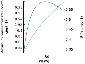
Maximum Power Transfer: When the impedance of the source, transmission line, and load are matched, maximum power is transferred from the source to the load. This is because the reflections at the load are minimized, and the power is not dissipated in the transmission line.
-
Minimizing Reflections: When the impedance of the load is not matched to the impedance of the transmission line, some of the power is reflected back towards the source. These reflections can cause signal distortion and reduce the overall efficiency of the system.
-
Reducing Standing Waves: When reflections occur in a transmission line, they can combine with the incident waves to create standing waves. Standing waves can cause voltage and current variations along the length of the transmission line, which can lead to signal distortion and even damage to the components.
Transmission Line Theory
To understand impedance matching, it is important to have a basic understanding of transmission line theory. A transmission line is a two-conductor system that is used to transmit electrical signals over long distances. The most common types of transmission lines are coaxial cables, twisted pair cables, and waveguides.
Characteristic Impedance
One of the most important parameters of a transmission line is its characteristic impedance, which is denoted by $Z_0$. The characteristic impedance is the ratio of the voltage to the current in a transmission line, and it depends on the physical properties of the conductors and the dielectric material between them.
For a lossless transmission line, the characteristic impedance is given by:
$Z_0 = \sqrt{\frac{L}{C}}$
where $L$ is the inductance per unit length and $C$ is the capacitance per unit length of the transmission line.
Reflection Coefficient
When a signal encounters a discontinuity in the impedance of a transmission line, some of the power is reflected back towards the source. The amount of power reflected depends on the reflection coefficient, which is denoted by $\Gamma$.
The reflection coefficient is given by:
$\Gamma = \frac{Z_L – Z_0}{Z_L + Z_0}$
where $Z_L$ is the impedance of the load and $Z_0$ is the characteristic impedance of the transmission line.
If the load impedance is equal to the characteristic impedance of the transmission line, the reflection coefficient is zero, and all of the power is transferred to the load. If the load impedance is not equal to the characteristic impedance, some of the power is reflected back towards the source.
Standing Wave Ratio
The standing wave ratio (SWR) is a measure of the amount of power reflected from the load back towards the source. It is defined as the ratio of the maximum voltage to the minimum voltage along the length of the transmission line.
The SWR is related to the reflection coefficient by:
$SWR = \frac{1 + |\Gamma|}{1 – |\Gamma|}$
An SWR of 1 indicates a perfect match between the load and the transmission line, while an SWR greater than 1 indicates a mismatch.
Impedance Matching Techniques
There are several techniques that can be used to match the impedance of a load to the characteristic impedance of a transmission line. Some of the most common techniques are:
Quarter-wave transformer
A quarter-wave transformer is a section of transmission line that is one-quarter wavelength long at the operating frequency. It can be used to match the impedance of a load to the characteristic impedance of a transmission line.
The impedance of the quarter-wave transformer is given by:
$Z_T = \sqrt{Z_0 Z_L}$
where $Z_0$ is the characteristic impedance of the transmission line and $Z_L$ is the impedance of the load.
Stub Matching
Stub matching is a technique that uses a short section of transmission line, called a stub, to cancel out the reactive component of the load impedance. The stub can be either open-circuited or short-circuited, and its length is chosen to provide the required reactance.
L-Network Matching
An L-network is a type of impedance matching network that consists of two reactive components, usually an inductor and a capacitor. The values of the components are chosen to match the impedance of the load to the characteristic impedance of the transmission line.
Pi-Network Matching
A pi-network is another type of impedance matching network that consists of three reactive components, usually two capacitors and an inductor. The values of the components are chosen to match the impedance of the load to the characteristic impedance of the transmission line.

Applications of Impedance Matching
Impedance matching is used in a wide range of applications, including:
Radio and Television Broadcasting
In radio and television broadcasting, impedance matching is used to ensure that the maximum amount of power is transferred from the transmitter to the antenna. This is important because any power that is not radiated by the antenna is wasted as heat in the transmission line.
Wireless Communications
In wireless communications, impedance matching is used to ensure that the maximum amount of power is transferred from the transmitter to the antenna, and from the antenna to the receiver. This is important because any power that is not transferred is lost as heat in the components.
Radar Systems
In radar systems, impedance matching is used to ensure that the maximum amount of power is transferred from the transmitter to the antenna, and from the antenna to the receiver. This is important because any power that is not transferred reduces the range and accuracy of the radar system.
Medical Imaging
In medical imaging systems, such as MRI and ultrasound, impedance matching is used to ensure that the maximum amount of power is transferred from the transmitter to the transducer, and from the transducer to the receiver. This is important because any power that is not transferred reduces the quality and resolution of the image.
Common Misconceptions about Impedance Matching
There are several common misconceptions about impedance matching that can lead to confusion and errors in the design and operation of transmission lines. Some of the most common misconceptions are:
Myth: Impedance Matching is Only Important at High Frequencies
While impedance matching is more critical at high frequencies, it is important at all frequencies. Even at low frequencies, impedance mismatches can cause reflections and reduce the efficiency of the system.
Myth: Impedance Matching is Only Important for Long Transmission Lines
Impedance matching is important for all transmission lines, regardless of their length. Even short transmission lines can have significant impedance mismatches that can cause reflections and reduce the efficiency of the system.
Myth: Impedance Matching is Only Important for Transmitters
Impedance matching is important for both transmitters and receivers. In a transmitter, impedance matching ensures that the maximum amount of power is transferred to the antenna, while in a receiver, impedance matching ensures that the maximum amount of power is transferred from the antenna to the receiver.
Conclusion
Impedance matching is a crucial concept in the design and operation of transmission lines. It ensures that the maximum amount of power is transferred from the source to the load, while minimizing reflections and signal distortion. There are several techniques that can be used to match the impedance of a load to the characteristic impedance of a transmission line, including quarter-wave transformers, stub matching, L-networks, and pi-networks.
Impedance matching is used in a wide range of applications, including radio and television broadcasting, wireless communications, radar systems, and medical imaging. It is important to understand the basic principles of impedance matching to ensure the efficient and reliable operation of these systems.
Frequently Asked Questions (FAQ)
-
What is impedance matching?
Impedance matching is the process of matching the impedance of a load to the characteristic impedance of a transmission line to ensure maximum power transfer and minimize reflections and signal distortion. -
Why is impedance matching important?
Impedance matching is important because it ensures that the maximum amount of power is transferred from the source to the load, while minimizing reflections and signal distortion. This improves the efficiency and reliability of the system. -
What are some common techniques for impedance matching?
Some common techniques for impedance matching include quarter-wave transformers, stub matching, L-networks, and pi-networks. -
What is the characteristic impedance of a transmission line?
The characteristic impedance of a transmission line is the ratio of the voltage to the current in the line, and it depends on the physical properties of the conductors and the dielectric material between them. -
What is the standing wave ratio (SWR)?
The standing wave ratio (SWR) is a measure of the amount of power reflected from the load back towards the source. It is defined as the ratio of the maximum voltage to the minimum voltage along the length of the transmission line. An SWR of 1 indicates a perfect match between the load and the transmission line, while an SWR greater than 1 indicates a mismatch.
No responses yet